Switches and jumpers on the terminal board, Figure 3.6, 4 control circuit wiring – Yaskawa AC Drive P1000 Bypass Technical Manual User Manual
Page 51
A
E
B
C
D
A – Drive side
B – Connect shield to ground terminal
of drive.
C – Insulation
D – Control device side
E – Shield sheath (insulate with tape)
F – Shield
Figure 3.6 Preparing the Ends of Shielded Cables
NOTICE: The analog signal wiring between the drive and the operator station or peripheral equipment should not exceed 50 meters when
using an analog signal from a remote source to supply the frequency reference. Failure to comply could result in poor system performance.
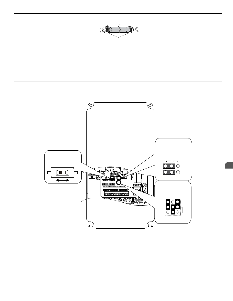
u
Switches and Jumpers on the Terminal Board
The terminal board is equipped with several switches used to adapt the drive I/Os to the external control signals.
shows the location of these switches.
Refer to Bypass and Drive Control I/O Connections on page 52
for setting instructions.
E(G) IG R+ R- S+ S-
S1 S2 S3 S4 S5 S6 S7 S8 SN SC SP
V+ AC A1 A2 A3 FM AM AC
24V
RP AC
M1 M2 M3 M4
MD ME MF
MA MB MC
Selection
V
AM
FM
I
Jumper S5
Terminal AM/FM Signal
DIP Switch S2
RS-422/485 Termination
Resistor
Off
On
Jumper S1
A1/A2/A3 Volt/Curr.
Selection
V
I
A1 A2 A3
Figure 3.7 Locations of Jumpers and Switches on the Terminal Board
3.4 Control Circuit Wiring
YASKAWA SIEP YAIP1B 01A YASKAWA AC Drive – P1000 Bypass Technical Manual
51
3
Electrical Installation