Cable length between bypass and motor, Ground wiring – Yaskawa AC Drive P1000 Bypass Technical Manual User Manual
Page 44
n
Cable Length Between Bypass and Motor
Voltage drop along the motor cable may cause reduced motor torque when the wiring between the bypass and the motor is
too long, especially at low frequency output. This can also be a problem when motors are connected in parallel with a fairly
long motor cable. Bypass output current will increase as the leakage current from the cable increases. An increase in leakage
current may trigger an overcurrent situation and weaken the accuracy of the current detection.
Adjust the carrier frequency according to
. If the motor wiring distance exceeds 100 m because of the system
configuration, reduce the ground currents.
Refer to C6-02: Carrier Frequency Selection on page 104
Table 3.2 Cable Length Between Bypass and Motor
Cable Length
50 m or less
100 m or less
Greater than 100 m
Carrier Frequency
12.5 kHz or less
5 kHz or less
2 kHz or less
Note:
1. When setting carrier frequency for bypasses running multiple motors, calculate cable length as the total wiring distance to all connected
motors.
2. Do not use a long distance shielded line if there is an overvoltage problem at start. Either lower the carrier frequency or switch on the
internal EMC filter if the power supply has a neutral ground.
n
Ground Wiring
Follow the precautions below when wiring the ground for one bypass or a series of bypasses.
WARNING! Electrical Shock Hazard. Before servicing, disconnect all power to the equipment. The internal capacitor remains charged even
after the power supply is turned off. The charge indicator LED will extinguish when the DC bus voltage is below 50 Vdc. To prevent electric
shock, wait for at least the time specified on the warning label, once all indicators are OFF, measure for unsafe voltages to confirm the drive
is safe prior to servicing.
WARNING! Electrical Shock Hazard. Make sure the protective earthing conductor complies with technical standards and local safety
regulations. Because the leakage current exceeds 3.5 mA, IEC 61800-5-1 states that either the power supply must be automatically
disconnected in case of discontinuity of the protective earthing conductor or a protective earthing conductor with a cross-section of at least
10 mm
2
(Cu) or 16 mm
2
(Al) must be used. Failure to comply may result in death or serious injury.
WARNING! Electrical Shock Hazard. Always use a ground wire that complies with technical standards on electrical equipment and minimize
the length of the ground wire. Improper equipment grounding may cause dangerous electrical potentials on equipment chassis, which could
result in death or serious injury.
WARNING! Electrical Shock Hazard. Be sure to ground the drive ground terminal (208 Vac bypass drive: ground to 100 Ω or less and 480
Vac bypass drive: ground to 10 Ω or less). Improper equipment grounding could result in death or serious injury by contacting ungrounded
electrical equipment.
NOTICE: Do not share the ground wire with other devices such as welding machines or large-current electrical equipment. Improper
equipment grounding could result in drive or equipment malfunction due to electrical interference.
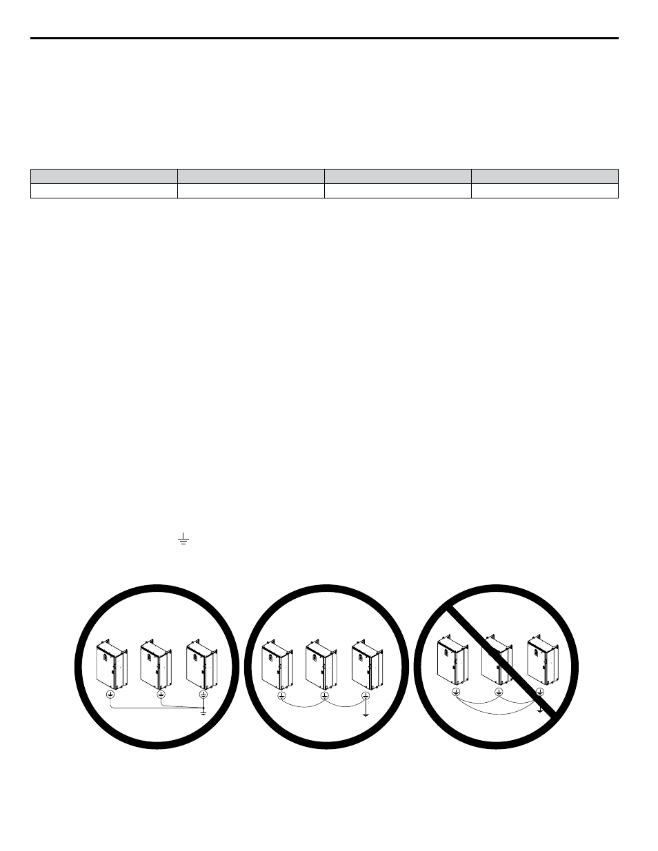
NOTICE: When using more than one drive, ground multiple drives according to instructions. Improper equipment grounding could result in
abnormal operation of drive or equipment.
when using multiple drives. Do not loop the ground wire.
The drive ground lug (terminal ) is connected to the enclosure. The enclosure ground lug must be connected to earth ground.
The drive has a second ground lug to accept the motor ground lead.
INCHES
D
SCALE
E
I
H
F
D
C
B
A
DATE
DATE
DATE
DATE
DATE
OF YASKAWA AMERICA INC.
WITHOUT THE EXPRESS WRITTEN CONSENT
COPIED OR DISCLOSED IN WHOLE OR IN PART
IN IT ARE CONFIDENTIAL, AND CANNOT BE
THIS DOCUMENT AND INFORMATION CONTAINED
TM
-
-
-
-
-
SEE BOM
SEE NOTES
XXX
XXX
XXX
XXX
XXX
XXX
XXX
XXX
XXXXXXX
OF
XXXXXXX
Figure 3.1 Ground Wiring for Multiple Bypass Units
3.3 Main Circuit Wiring
44
YASKAWA SIEP YAIP1B 01A YASKAWA AC Drive – P1000 Bypass Technical Manual