Control circuit wiring, Electronic bypass control terminal board a2, 4 control circuit wiring – Yaskawa AC Drive P1000 Bypass Technical Manual User Manual
Page 46: Refer to control
3.4 Control Circuit Wiring
Note:
Refer to the documentation packaged with the P1000 Bypass and labels placed in the bypass enclosure for procedures required to safely
and properly wire the bypass and drive control circuits.
u
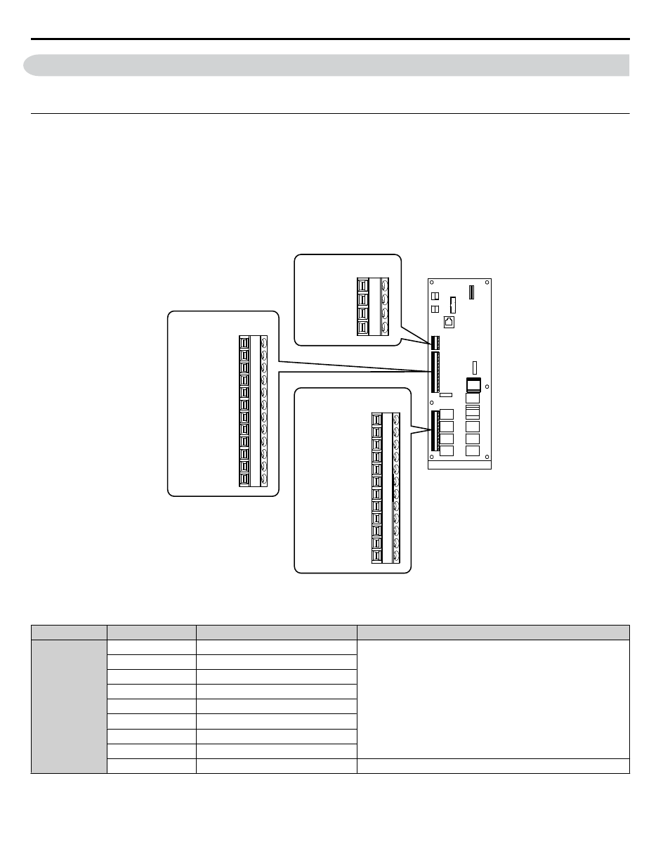
Electronic Bypass Control Terminal Board A2
WARNING! Sudden Movement Hazard. Always check the operation and wiring of control circuits after being wired. Operating a P1000
Bypass with untested control circuits could result in death or serious injury.
WARNING! Sudden Movement Hazard. Confirm the drive I/O signals and external sequence before starting test run. Setting parameter
Z1-01 may change the I/O terminal function automatically from the default setting.
Refer to Application Selection on page 75
to comply may result in death or serious injury.
The functions of the control circuit terminals are shown in
The control circuit terminals are typically located on the interior left side of the bypass enclosure and are arranged as shown
in
.
12. SHIELD
11. SHIELD
10. IG24
9. IG24
8. DI-8
7. DI-7
6. DI-6
5. DI-5
4. DI-4
3. DI-3
2. DI-2
1. DI-1
TB2
TB3
4. SHIELD
3. TXRX-
2. TXRX+
1. IG5
TB1
12. DO-10 NO
11. DO-10 C
10. DO-10 NC
9. DO-9 NO
8. DO-9 C
7. DO-9 NC
6. DO-8 NO
5. DO-8 C
4. DO-8 NC
3. DO-7 NO
2. DO-7 C
1. DO-7 NC
Figure 3.2 Control Circuit Terminal Board A2 Arrangement
Table 3.3 P1000 Bypass Control Circuit Terminal Board A2
Type
Signal Name
Description
Specification
Digital Inputs
DI-1
Digital Input 1
Dry contact rated, photocoupler sinking input to IG, 24 Vdc 8 mA,
ground fault protected
DI-2
Digital Input 2
DI-3
Digital Input 3
DI-4
Digital Input 4
DI-5
Digital Input 5
DI-6
Digital Input 6
DI-7
Digital Input 7
DI-8
Digital Input 8
IG24
Isolated Ground
Digital Input Common
3.4 Control Circuit Wiring
46
YASKAWA SIEP YAIP1B 01A YASKAWA AC Drive – P1000 Bypass Technical Manual