H3: multi-function analog inputs – Yaskawa AC Drive P1000 Bypass Technical Manual User Manual
Page 117
Setting 14: Fault Reset
When the drive detects a fault condition, the fault output contact closes, the drive output shuts off, and the motor coasts to
stop (specific stopping methods can be selected for some faults such as L1-04 for motor overheat). After removing the Run
command, clear the fault either by pressing the RESET key on the HOA keypad or closing a digital input configured as a Fault
Reset (H1-oo = 14).
Note:
Remove the Run command prior to resetting a fault. Fault Reset commands are ignored while the Run command is present.
Setting 19: PID Disable
Close a digital input to indefinitely disable the PID function. When the input is released, the drive resumes PID operation.
Refer to PID Block Diagram on page 93
Setting 24: External Fault
The External fault command stops the drive when problems occur with external devices.
To use the External fault command, set one of the multi-function digital inputs to 24. The HOA keypad will display EFo
where o is the number of the terminal to which the external fault signal is assigned.
For example, if an external fault signal is input to terminal DI-3, “EF3” will be displayed.
The conditions of setting 24 are:
• Terminal status is normally open
• Detection condition is always detected
• Stopping method is coast to stop.
Setting 60: DC Injection Braking Command
DC Injection Braking is activated when a DC Injection Braking command is input while the drive is stopped. DC Injection
Braking is released when a Run command or a Jog command is input.
Refer to b2: DC Injection Braking and Short Circuit
for details on setting up the DC Injection Braking function.
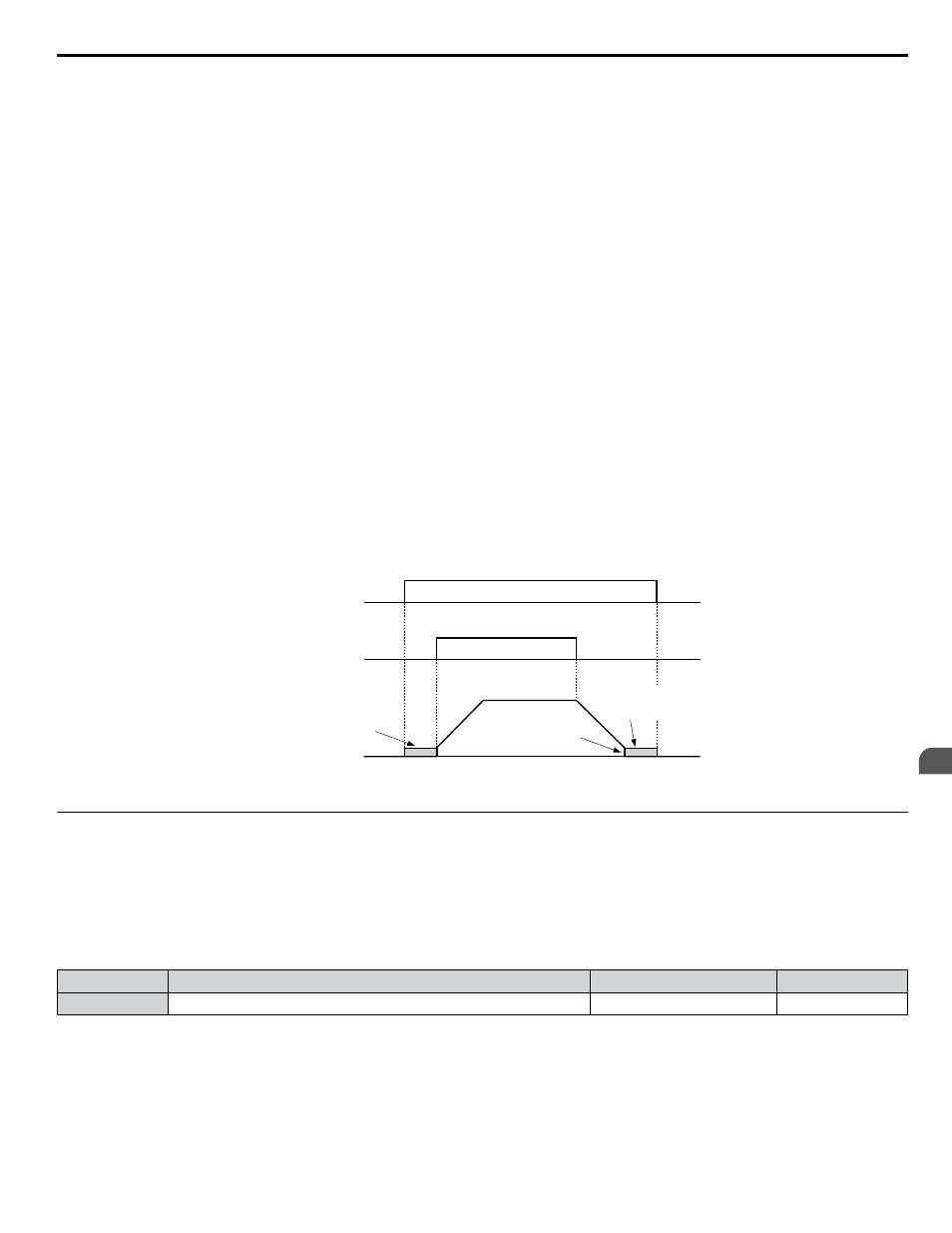
The diagram below illustrates DC Injection Braking:
DC Injection braking
command
FWD Run command
Output frequency
DC Injection
braking
DC Injection
braking
DC Injection Braking
Start Frequency
(b2-01)
OFF
OFF
OFF
OFF
ON
ON
Figure 5.22 DC Injection Braking Input Timing Diagram
u
H3: Multi-Function Analog Inputs
The drive is equipped with three multi-function analog input terminals: A1, A2, and A3.
Refer to Multi-Function Analog
Input Terminal Settings on page 120
for a listing of the functions that can be set to these terminals.
n
H3-01: Terminal A1 Signal Level Selection
Selects the input signal level for analog input A1. Set jumper S1 on the terminal board accordingly for voltage input or current
input.
No.
Name
Setting Range
Default
H3-01
Terminal A1 Signal Level Selection
0 to 3
0
Setting 0: 0 to 10 V with Zero Limit
The input level is 0 to 10 Vdc with zero limit. The minimum input level is limited to 0%, so that a negative input signal due
to gain and bias settings will be read as 0%.
Setting 1: 0 to 10 V without Zero Limit
The input level is 0 to 10 Vdc without zero limit. If the resulting voltage is negative after being adjusted by gain and bias
settings, then the motor will rotate in reverse.
5.7 H: Terminal Functions
YASKAWA SIEP YAIP1B 01A YASKAWA AC Drive – P1000 Bypass Technical Manual
117
5
Programming