Bypass analog outputs – Yaskawa AC Drive P1000 Bypass Technical Manual User Manual
Page 47
Type
Signal Name
Description
Specification
Digital Outputs
120 Vac
DO-1
Digital Output 1
(Factory use only) 120 Vac, 66 VA sealed, 1650 inrush
DO-2
Digital Output 2
DO-3
Digital Output 3
DO-4
Digital Output 4
DO-5
Digital Output 5
Digital Outputs
DO-6
Digital Output 6
Relay, dry contact, form C, 30 Vdc or 120 Vac,
DO-6 (factory use only), 3.7 Amp 360 VA,
DO-7 to DO-10 for customer use, 2 Amp
DO-7
Digital Output 7
DO-8
Digital Output 8
DO-9
Digital Output 9
DO-10
Digital Output 10
lists the available control circuit input terminals on the drive. Text in parenthesis indicates the default setting for
each multi-function input.
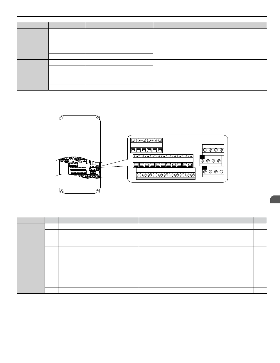
The drive control circuit terminals are arranged as shown in
E(G) IG R+ R- S+ S-
S1 S2 S3 S4 S5 S6 S7 S8 SN SC SP
V+ AC A1 A2 A3 FM AM AC
24V
RP AC
M1 M2 M3 M4
MD ME MF
MA MB MC
E(G) IG R+ R- S+ S-
S1 S2 S3 S4 S5 S6 S7 S8 SN SC SP
V+ AC A1 A2 A3 FM AM AC
24V
RP AC
M1 M2 M3 M4
MD ME MF
MA MB MC
Figure 3.3 Drive Control Circuit Terminal Board Arrangement
Table 3.4 Drive Control Circuit Terminal Board A1
Type
No.
Terminal Name (Function)
Function (Signal Level) Default Setting
Page
Frequency
Reference
Inputs
+V
Power supply for analog inputs
10.5 Vdc (maximum allowable current 20 mA)
A1
Multi-function analog input 1
(Frequency reference bias)
• 0 to 10 Vdc/100% (input impedance: 20 kΩ)
• 4 to 20 mA/100%, 0 to 20 mA/100% (input impedance: 250 Ω)
• Voltage or current input must be selected by Jumper S1 and H3-01.
A2
Multi-function analog input 2
(Frequency reference bias)
• 0 to 10 Vdc/100% (input impedance: 20 kΩ)
• 4 to 20 mA/100%, 0 to 20 mA/100% (input impedance: 250 Ω)
• Voltage or current input must be selected by Jumper S1 and H3-09.
A3
Multi-function analog input 3
(Auxiliary frequency reference 1)
• -10 to 10 Vdc, 0 to 10 Vdc (input impedance: 20 kΩ)
• 4 to 20 mA, 0 to 20 mA (input impedance: 250 Ω)
• Voltage or current input must be selected by jumper S1 and H3-05.
AC
Frequency reference common
0 V
FE
Ground for shielded lines and option cards
–
–
u
Bypass Analog Outputs
There are two analog outputs that can be configured for a signal level of 0 to 10 Vdc or 4 to 20 mA. The signal level is controlled
by the position of jumpers J2 and J3 on Control PCB A2 and by the values set to drive parameters H4-07 and H4-08.
3.4 Control Circuit Wiring
YASKAWA SIEP YAIP1B 01A YASKAWA AC Drive – P1000 Bypass Technical Manual
47
3
Electrical Installation