Bypass component descriptions, Bypass front control panel, 4 bypass component descriptions – Yaskawa AC Drive P1000 Bypass Technical Manual User Manual
Page 32: Input circuit breaker, Contactors, Overload relay, Control power transformer, Electronic bypass control logic
1.4 Bypass Component Descriptions
u
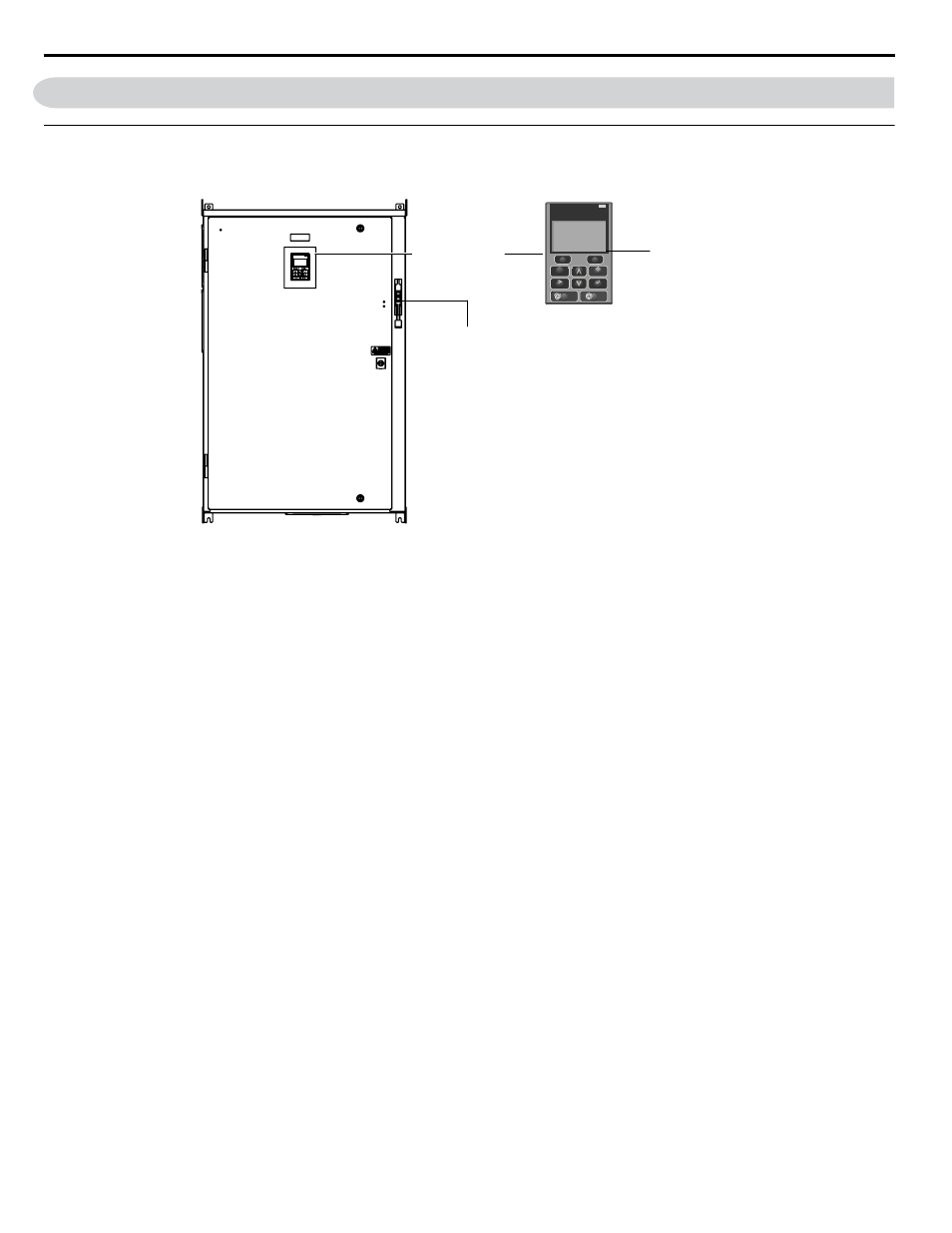
Bypass Front Control Panel
The external appearance and component names of the P1000 Bypass are shown in
Main disconnect handle
(shown in OFF position)
HOA keypad
F2
F1
ESC
M
M
AUTO
OFF
ENTER
RESET
ALM
DIGITAL OPERATOR JVOP-183
HAND
Alpha-numeric
LCD display
Figure 1.3 P1000 Bypass Control Panel with Keypad Operator Controls
Refer to Using the HOA Keypad on page 59
for details on the HOA keypad.
n
Input Circuit Breaker
Electrically located on the input power side of the bypass, the input circuit breaker and its main disconnect handle provide a
means of disconnecting the bypass from line power for equipment maintenance. The handle must be in the OFF position to
open the bypass enclosure door. The handle can be locked in the OFF position using a padlock.
n
Contactors
The P1000 Bypass is a 3-contactor bypass circuit employing IEC rated contactors in an electrically interlocked arrangement
to allow mutually exclusive operation in Drive or Bypass modes.
The control logic and “soft start” characteristic of the drive limit the drive input and output contactors to motor FLA current
or less. The bypass contactor is exposed to motor inrush current (LRA) when starting the motor across-the-line and therefore
may require a higher current rating than the drive input and output contactors.
n
Overload Relay
The adjustable thermal overload relay (OLR) provides overload protection for the motor in Drive and Bypass operating modes.
The bypass three-phase output power connection to the motor is made to the output terminals of the OLR. The OLR is set up
in the factory to be a manual reset device, requiring operator attention if an overload trip-out is experienced.
n
Control Power Transformer
A Control Power Transformer (CPT) is provided to power the P1000 Bypass 120 Vac control circuit. The VA capacity is
determined by the control circuit and optional functions specified for the unit. The CPT primary is fused in both legs, the
secondary is fused when required by NEC (transformer VA and wire size dependent). One side of the transformer secondary
is grounded to the bypass enclosure.
n
Electronic Bypass Control Logic
Operating elements such as indicating LEDs, selector buttons, and control logic are incorporated into a PCB assembly to
eliminate the potential for loose wires after shipment.
The operating elements are located on PCB A3 and the control logic PCB A2 is mounted to the left-hand side of the enclosure
and contains the control circuit field wiring terminal blocks TB1 through TB3.
1.4 Bypass Component Descriptions
32
YASKAWA SIEP YAIP1B 01A YASKAWA AC Drive – P1000 Bypass Technical Manual