Yaskawa AC Drive P1000 Bypass Technical Manual User Manual
Page 129
n
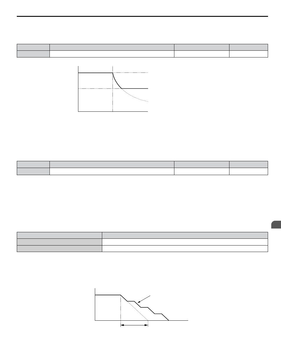
L3-03: Stall Prevention Limit during Acceleration
The Stall Prevention level is automatically reduced when the motor is operated in the constant power range. L3-03 sets the
lower limit for this reduction as a percentage of the drive rated current.
No.
Name
Setting Range
Default
L3-03
Stall Prevention Limit during Acceleration
0 to 100%
50%
Stall Prevention level during Acceleration
Output frequency
L3-03
E1-06
Base frequency
L3-02
Figure 5.32 Stall Prevention Level and Limit During Acceleration
n
L3-04: Stall Prevention Selection during Deceleration
Stall Prevention during deceleration controls the deceleration based on the DC bus voltage and prevents an overvoltage fault
caused by high inertia or rapid deceleration.
No.
Name
Setting Range
Default
L3-04
Stall Prevention Selection During Deceleration
0 to 5
<1>
1
<1> Setting 3 is not available in models 4A0930 or 4A1200.
Setting 0: Disabled
The drive decelerates according to the set deceleration time. With high inertia loads or rapid deceleration, an overvoltage fault
may occur. If an overvoltage fault occurs, use dynamic braking options or switch to another L3-04 selection.
Setting 1: General-purpose Stall Prevention
The drive tries to decelerate within the set deceleration time. The drive pauses deceleration when the DC bus voltage exceeds
the Stall Prevention level and then continues deceleration when the DC bus voltage drops below that level. Stall Prevention
may be triggered repeatedly to avoid an overvoltage fault. The DC bus voltage level for Stall Prevention depends on the input
voltage setting E1-01.
Drive Input Voltage
Stall Prevention Level during Deceleration
208 Vac Bypass Drives
377 Vdc
480 Vac Bypass Drives
754 Vdc
Note:
1. Do not use this setting in combination with a Dynamic Braking Resistor or other dynamic braking options. If Stall Prevention during
deceleration is enabled, it will be triggered before the braking resistor option can operate.
2. This method may lengthen the total deceleration time compared to the set value. If this is not appropriate for the application consider
using a dynamic braking option.
illustrates the function of Stall Prevention during deceleration.
Output Frequency
Deceleration characteristics
when Stall Prevention was
triggered during deceleration
Time
specified deceleration time
Figure 5.33 Stall Prevention During Deceleration
5.8 L: Protection Functions
YASKAWA SIEP YAIP1B 01A YASKAWA AC Drive – P1000 Bypass Technical Manual
129
5
Programming