Main circuit wiring, Factory recommended branch circuit protection, Drive main circuit terminal functions – Yaskawa AC Drive P1000 Bypass Technical Manual User Manual
Page 43: Wire gauge and tightening torque specifications, Main input circuit and motor wiring, 3 main circuit wiring
3.3 Main Circuit Wiring
Note:
Refer to the documentation packaged with the P1000 Bypass and labels placed in the Bypass enclosure for procedures required to safely
and properly wire the Bypass main circuit.
NOTICE: Do not solder the ends of wire connections to the bypass. Soldered wiring connections can loosen over time. Improper wiring
practices could result in malfunction due to loose terminal connections.
NOTICE: Do not switch the bypass input to start or stop the motor. Frequently switching the bypass on and off shortens the life of the DC
bus charge circuit and the DC bus capacitors, and can cause premature bypass failures. For the full performance life, refrain from switching
the bypass on and off more than once every 30 minutes.
u
Factory Recommended Branch Circuit Protection
WARNING! Fire Hazard. Branch Circuit protection is required to be installed according to applicable local codes and the requirements listed
on the P1000 Bypass nameplate. Failure to comply could result in fire and damage to the bypass and drive or injury to personnel. The P1000
Bypass is suitable for use on a circuit capable of delivering not more than 100,000 RMS symmetrical amperes, 208 Vac and 480 Vac with
the circuit breaker option or when protected by class J or class L fuses as specified on the P1000 Bypass nameplate.
Yaskawa recommends installing branch circuit protection according to maintain compliance with UL508C. Semiconductor
protective type fuses are preferred. Alternate branch circuit protection devices are also listed in this manual.
u
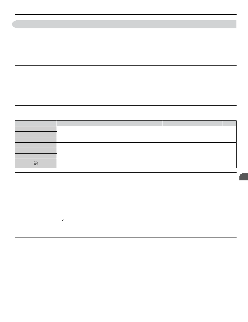
Drive Main Circuit Terminal Functions
Table 3.1 Main Circuit Terminal Functions
Terminal
Description
Function
Page
R/L1
Main circuit power supply input
Connects line power to the bypass
S/L2
T/L3
U/T1
Drive output
Connects to the motor
V/T2
W/T3
For 200 V Class: 100 Ω or less
For 400 V Class: 10 Ω or less
Grounding terminal
u
Wire Gauge and Tightening Torque Specifications
Note:
1. For 0 to 100 A, use a minimum of 60 °C - 75 °C copper wire.
2. For above 100 A, use a minimum of 75 °C copper wire.
3. Wire gauge recommendations based on drive continuous current ratings using 75 °C 600 Vac vinyl-sheathed wire assuming ambient
temperature within 40 °C and wiring distance less than 100 m.
• Consider the amount of voltage drop when selecting wire gauges. Increase the wire gauge when the voltage drop is greater
than 2% of motor rated voltage. Ensure the wire gauge is suitable for the terminal block. Use the following formula to
calculate the amount of voltage drop:
Line drop voltage (V) = 3 × wire resistance (Ω/km) × wire length (m) × current (A) × 10
-3
•
•
Refer to UL Standards Compliance on page 337
for information on UL compliance.
u
Main Input Circuit and Motor Wiring
This section outlines the various steps, precautions, and checkpoints for wiring the main circuit terminals and motor terminals.
WARNING! Electrical Shock Hazard. Do not connect the AC power line to the bypass output terminals. Failure to comply could result in
death or serious injury by fire as a result of bypass damage from line voltage application to output terminals.
NOTICE: When connecting the motor to the output terminals T1, T2, and T3, the phase order for the drive and motor should match. Failure
to comply with proper wiring practices may cause the motor to run in reverse if the phase order is backward.
NOTICE: Do not connect phase-advancing capacitors or LC/RC noise filters to the output circuits. Failure to comply could result in damage
to the drive, phase-advancing capacitors, LC/RC noise filters or ground fault circuit interrupters.
NOTICE: Route motor leads U/T1, V/T2, and W/T3 separate from all other leads to reduce possible interference-related issues. Failure to
comply may result in abnormal operation of bypass and nearby equipment.
3.3 Main Circuit Wiring
YASKAWA SIEP YAIP1B 01A YASKAWA AC Drive – P1000 Bypass Technical Manual
43
3
Electrical Installation