Varispeed g7 connection example, 5 operation with the drive connected, Interlock with the drive on page 97 – Yaskawa D1000 Series Power Regenerative Converter User Manual
Page 96
4.5 Operation with the Drive Connected
96
YASKAWA ELECTRIC TOEP C710656 07C YASKAWA Power Regenerative Converter - D1000 Instruction Manual
Note: For information on connecting other control circuit I/O terminals, refer to the Quick Start Guide for the drive that is connected to
the converter.
WARNING! Sudden Movement Hazard. Ensure all I/O circuits such as start/stop and safety circuits are set properly prior to application
of main power to the converter. Failure to comply could result in sudden machine operation, which could result in death or serious
injury.
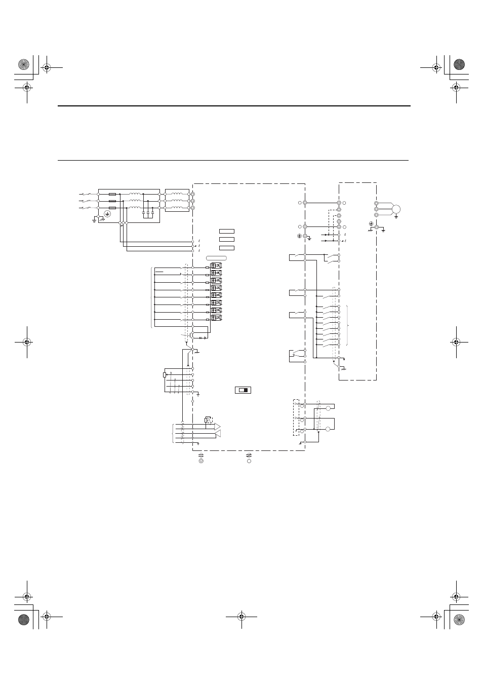
◆ Varispeed G7 Connection Example
Figure 4.4
Figure 4.5 Standard Connection Diagram with Varispeed G7 (Example for CIMR-D4A0185)
WARNING! Sudden Movement Hazard. Ensure all I/O circuits such as start/stop and safety circuits are set properly prior to application
of main power to the converter. Failure to comply could result in sudden machine operation, which could result in death or serious injury.
<1> Do not use a line longer than 10 m (32.8 ft) to connect the input-side AC reactor and the converter.
<2> Use the specified AC reactor and harmonic filter module. Non-specified devices may cause erroneous operation.
<3> Do not use a DC bus line that is longer than 5 m (16.4 ft) to connect the converter and drive.
<4> Sequence the operation so that the converter starts operation before the drive when power is applied. Sequence the stopping
operation to turn off the drive first, then the motor, and finally the converter. Operating the drive without operating the converter or
turning off the power supply unit during operation may trigger a converter fault.
<5> Do not connect a power supply to the drive AC power supply terminals (R/L1, S/L2, and T/L3).
<6> For information on an interlock with the drive, refer to
Interlock with the Drive on page 97
<7> This figure shows an example of a sequence input to S1 through S8 using a non-powered relay or an NPN transistor. Install the wire
link between terminals SC-SP for Sink mode and SC-SN for Source mode. Leave it out for external power supply. Never short
terminals SP and SN as doing so will damage the converter.
D1000
+
-
Ground
E(G)
MA
MB
MC
(Reserved)
(Reserved)
(Reserved)
Shield ground terminal
Converter
Fault relay output
250 Vac, max. 1 A
30 Vdc, max. 1 A
(min. 5 Vdc, 10 mA)
+V
A1
A2
A3
AC
R+
R-
S+
S-
IG
V
I
MEMOBUS/
Modbus Communication
RS-422/RS-485
max. 115.2 kbps
-V
Power supply
+10.5 Vdc, max. 20 mA
Power supply, -10.5 Vdc,
max. 20 mA
Analog Input 1
Analog Input 2
Analog Input 3
DIP Switch S1
Termination resistor
(120 Ω, 1/2 W)
DIP Switch S2
R/L1
S/L2
T/L3
CN5-A
CN5-B
CN5-C
S1 Forward Run / Stop
S2 Reverse Run / Stop
S3 External fault
S4 Fault reset
S5
S6
S7
S8
SC
Sequence common
Multi-function
digital inputs
Shield wire
connection terminal
E(G)
Varispeed G7
Drive
+
R/L1
1
S/L2
T/L3
-
A
B
IM
U/T1
V/T2
W/T3
Ground
Motor
S9
S10
S11
S12
r1/ 11
1/ 21
t1/ 31
Three-
Phase
Power
Supply
Input-side AC
reactor
Harmonic Filter Module
U
V
W
X
Y
Z
GFCI
or
MCCB
X
Y
Z
R/L1
S/L2
T/L3
r
t
<1><2>
<3>
<3>
<6>
<4>
<5>
r /
1
/
2
Multi-function relay output
(During MC on)
250 Vac, max. 1 A
30 Vdc, max. 1 A
(min. 5 Vdc, 10 mA)
Multi-function relay output
(Operation Ready)
250 Vac, max. 1 A
30 Vdc, max. 1 A
(min. 5 Vdc, 10 mA)
Multi-function relay
output (During Run 1)
250 Vac, max. 1 A
30 Vdc, max. 1 A
(min. 5 Vdc, 10 mA)
Option card
connectors
M1
M2
M3
M4
M5
M6
Control Circuit
S1
S2
S3
S4
S5
S6
S7
S8
SC
<7>
+24 V
RUN-SB
STOP
External fault
Fault reset
(Reserved)
(Reserved)
External Baseblock
(Reserved)
Multi-function
digital inputs
(default setting)
Sink / Source mode
selection wire link
(default: Sink)
SP
SN
0 V
FM
AM
AC
E (G)
Multi-function analog
output 1
(Output frequency)
-10 to +10 Vdc (2 mA) or
4 to 20 mA
Multi-function analog
output 2
(Output current)
-10 to +10 Vdc (2 mA) or
4 to 20 mA
FM
AM
shielded line
twisted-pair shielded line
main circuit terminal
control circuit terminal
-
+
-
YAI
TOEP_C710656_07C_2_0.book 96 ページ 2015年1月9日 金曜日 午後6時23分