Yaskawa D1000 Series Power Regenerative Converter User Manual
Page 188
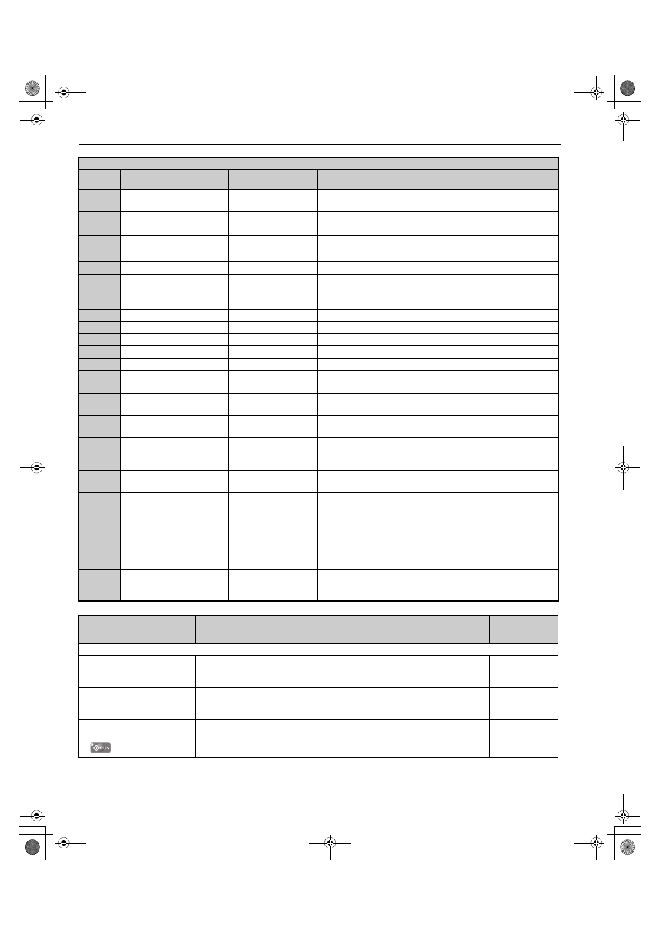
B.2 Parameter Tables
188
YASKAWA ELECTRIC TOEP C710656 07C YASKAWA Power Regenerative Converter - D1000 Instruction Manual
6
Ready
Drive Ready
Closed: Power up is complete and the converter is ready to accept a Run
command.
7
DC bus undervoltage
DC Bus Undervolt
Closed: DC bus voltage is below the Uv trip level set in L2-05.
8
During baseblock (N.O.)
BaseBlk 1
Closed: Converter has entered the baseblock state (no output voltage).
E
Fault
Fault
Closed: Fault occurred.
F
Through mode
Not Used
Set this value when using the terminal in the pass-through mode.
10
Minor fault
Minor Fault
Closed: An alarm has been triggered.
11
Fault reset command active
Reset Cmd Active
Closed: A command has been entered to clear a fault via the input
terminals or from the serial network.
12
Timer output
Timer Output
Closed: Timer output.
1B
During baseblock (N.C.)
BaseBlk 2
Open: Converter has entered the baseblock state (no output voltage).
1D
During Regeneration
Regenerating
Closed: Motor is regenerating energy into the converter.
1E
Restart enabled
Dur Flt Restart
Closed: An automatic restart is performed
20
Drive overheat pre-alarm (oH) OH Prealarm
Closed: Heatsink temperature exceeds the parameter L8-02 value.
24
Fuse Blowout Detection
FUA/FUD Detect
Closed: Fuse burnout detected.
25
During Run 1
During RUN 1
Closed: The drive is ready to operate.
26
During MC ON
MC On
Closed: The magnetic contactor is closed.
27
Converter Overload Warning
(oL2)
OL2 Pre-alarm
Closed: There is an overload warning.
2F
Maintenance Period
Maintenance
Closed: It is time to perform maintenance on the cooling fan, electrolytic
capacitor, and inrush prevention relay.
30
During Motoring Limit
Torque Limit
Closed: When the motoring limit has been reached.
39
Power Consumption
Pulse Output Energy
Pulse Out
Output units are determined by H2-06. Outputs a pulse every 200 ms to
indicate the kWh count.
3A
Regenerated Power
Pulse Output RegEn
Pulse Out
Outputs a pulse to indicate the regenerated power.
3B
Alarm 2
Minor Fault 2
Closed: Alarm occurred (excluding Uv, AUv, Fdv, SrC, and PAUv).
Note: This setting is available in converter software versions
PRG:902003 or later.
3C
LOCAL/REMOTE status
Local
Open: REMOTE
Closed: LOCAL
4D
oH Pre-alarm time limit
OH Pre-Alarm
Closed: oH pre-alarm time limit has passed.
60
Internal cooling fan alarm
Fan Alrm Det
Closed: Internal cooling fan alarm
100 to 160
Function 0 to 60 with inverse
output
–
Inverts the output switching of the multi-function output functions.
Set the last two digits of 1 to reverse the output signal of that
specific function.
No.
(Address
Hex)
Name
LCD Display
Description
Values
H3: Multi-Function Analog Inputs
H3-01
(410H)
Terminal A1 Signal
Level Selection
Term A1 Level
0: 0-10V, (LowLim=0)
1: 0-10V, (BipolRef)
0: 0 to 10 V
1: -10 to 10 V
Default: 0
Min.: 0
Max.: 1
H3-02
(434H)
Terminal A1
Function Selection
Term A1 FuncSel
Sets the function of terminal A1.
Default: F
Min.: F
Max.: 19
H3-03
(411H)
Terminal A1 Gain
Setting
Terminal A1 Gain
Sets the level of the input value selected in H3-02 when 10
V is input at terminal A1.
Default: 100.0%
Min.: -999.9%
Max.: 999.9%
H2 Multi-Function Relay Output Settings
H2-
Setting
Function
LCD Display
Description
TOEP_C710656_07C_2_0.book 188 ページ 2015年1月9日 金曜日 午後6時23分