U1 - 72 – Yaskawa D1000 Series Power Regenerative Converter User Manual
Page 197
B.2 Parameter Tables
YASKAWA ELECTRIC TOEP C710656 07C YASKAWA Power Regenerative Converter - D1000 Instruction Manual
197
B
U1-58
(1087H)
Power Supply
Frequency
AC
Frequency
Shows the frequency on the power supply side.
10 V: Rated
Frequency
0.1 Hz
U1-59
(1088H)
Power Supply
Current Reference
AC Current
Ref
Shows the current reference on the power supply side.
10 V: Rated
Input Current
1 A
U1-60
(1089H)
Power Factor
Power
Factor
Shows the power factor.
10 V: 100%
1%
U1-61
(108AH)
Active Current
Active
Current
Shows the active current.
10 V: 100.0%
0.1%
U1-62
(108BH)
Reactive Current
Reactive
Current
Shows the reactive current.
10 V: 100.0%
0.1%
U1-63
(108CH)
DC Bus Voltage
Reference (After
SFS)
DC Volt
SFS Out
Shows the DC bus voltage reference after the soft starter.
200 V Class
10 V: 400 V
400 V Class
10 V: 800 V
1 V
U1-64
(108DH)
Avr Input
(Voltage
Deviation)
AVR Input Shows the Avr input.
200 V Class
10 V: 400 V
400 V Class
10 V: 800 V
1 V
U1-65
(108EH)
Avr Output
AVR
Output
Shows the Avr output.
10 V: 100.0%
0.01%
U1-66
(108FH)
Control Voltage
Reference (Vq)
Voltage Ref
(Vq)
Shows the control voltage reference (Vq) in the converter for the current
control on the power supply side.
200 V Class
10 V: 200 V
400 V Class
10 V: 400 V
1 V
U1-67
(1090H)
Control Voltage
Reference (Vd)
Voltage Ref
(Vd)
Shows the control voltage reference (Vd) in the converter for the current
control on the power supply side.
200 V Class
10 V: 200 V
400 V Class
10 V: 400 V
1 V
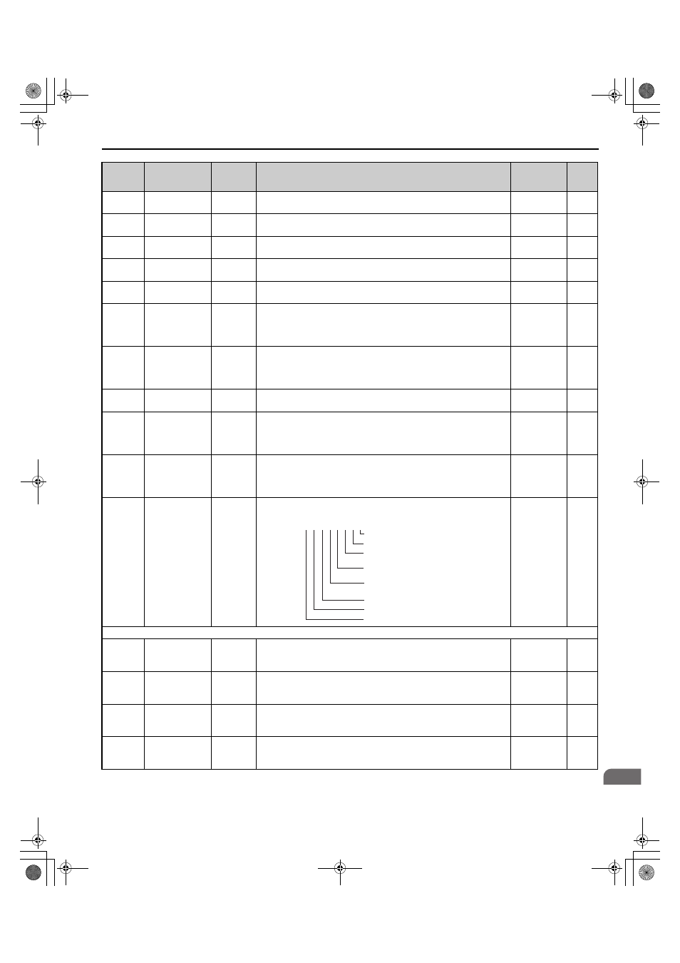
U1-72
(1095H)
Input Power
Supply
Information
AC Supply
Status
Shows information on the input power supply.
No signal
output
available
–
U2: Fault Trace
U2-01
(80H)
Current Fault
Current
Fault
Displays the current fault.
No signal
output
available
–
U2-02
(81H)
Previous Fault
Last Fault
Displays the previous fault.
No signal
output
available
–
U2-11
(8AH)
Input Terminal
Status at Previous
Fault
Input Term
Sts
Displays the input terminal status at the previous fault. Displayed as in
U1-10.
No signal
output
available
–
U2-12
(8BH)
Output Terminal
Status at Previous
Fault
Output
Term Sts
Displays the output status at the previous fault. Displays the same status
displayed in U1-11.
No signal
output
available
–
No.
(Address
Hex)
Name
LCD
Display
Description
Analog
Output
Level
Unit
U1 - 72=
0 0 0 0 0 0 0 0
Bit 0: AUv reset. (0: Not completed, 1: Reset)
Bit 1: PF3 reset (0: Not completed, 1: Reset)
Bit 2: Rated frequency detection
(0: Not completed, 1: Completed)
Bit 3: Phase order detection
(0: Not completed, 1: Completed)
Bit 4: Power supply established
(0: Not completed, 1: Completed)
Bit 5: Fdv detection (0: Not detected, 1: Detected)
Bit 6: PF3 detection (0: Not detected, 1: Detected)
Bit 7: Reserved.
TOEP_C710656_07C_2_0.book 197 ページ 2015年1月9日 金曜日 午後6時23分