Yaskawa D1000 Series Power Regenerative Converter User Manual
Page 117
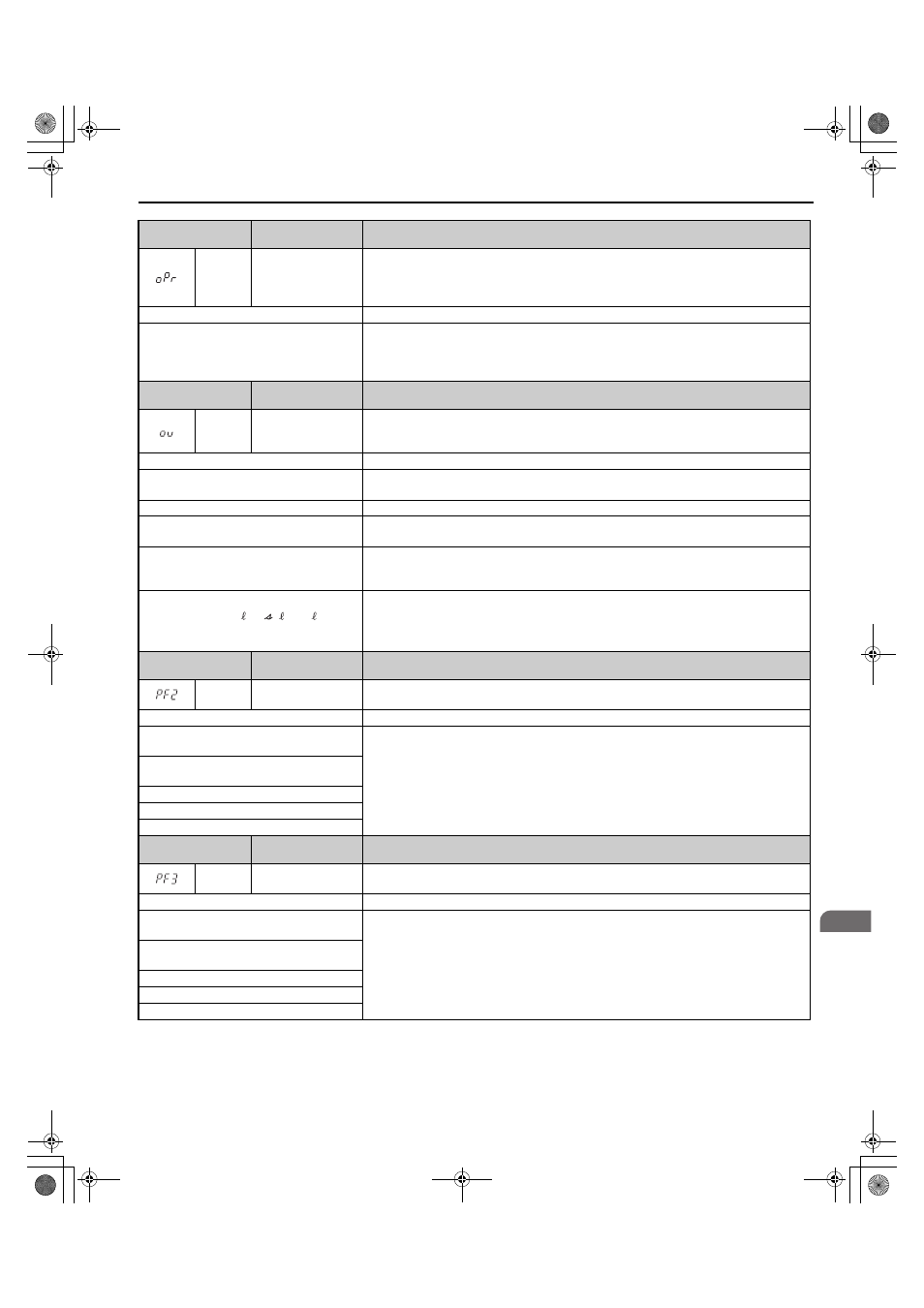
5.3 Fault Detection
YASKAWA ELECTRIC TOEP C710656 07C YASKAWA Power Regenerative Converter - D1000 Instruction Manual
117
Tr
ou
blesh
oot
ing
5
Digital Operator
Display
Fault Name
Details
oPr
External Digital
Operator Connection
Fault
The external operator has been disconnected from the converter.
Note: An oPr fault will occur when all of the following conditions are true:
• Output is interrupted when the operator is disconnected (o2-06 = 1).
• The Run command is assigned to the operator (b1-02 = 0 and LOCAL has been selected).
Cause
Possible Solution
External operator is not properly connected to
the converter.
• Check the connection between the operator and the converter.
• Replace the cable if damaged.
• Turn off the input power and disconnect the operator. Reconnect the operator and reapply
converter input power.
Digital Operator
Display
Fault Name
Details
ov
Overvoltage
Voltage in the DC bus has exceeded the overvoltage detection level.
• 200 V Class: Approximately 410 V
• 400 V Class: Approximately 820 V
Cause
Possible Solution
A momentary power loss occurred.
Investigate and correct the cause and reset the fault.
Refer to
Diagnosing and Resetting Faults on page 131
for details.
The regenerative load is too large.
Reduce the regenerative load.
Input power voltage is too high.
• Check the voltage.
• Lower input power voltage within the limits listed in the specifications.
Converter fails to operate properly due to noise
interference.
• Review the list of possible solutions provided for controlling noise.
• Review the section on handling noise interference and check the control circuit lines, main
circuit lines, and ground wiring.
The wiring of the power supply voltage
detection circuits (
) and
the wiring of the main circuit terminals
(R/L1, S/L2, and T/L3) is not correct.
Correct the wiring.
Digital Operator
Display
Fault Name
Details
PF2
Input Power Supply
Fault
Abnormal oscillation in the main circuit DC bus continued. (Applies when L8-65 is set to 1 or 2.)
Cause
Possible Solution
The fluctuation in the voltage of the input
power supply is too large.
Investigate and correct the cause and reset the fault.
Refer to
Diagnosing and Resetting Faults on page 131
A phase loss occurred in the input power
supply.
The capacity of the power supply is too small.
The wiring is too long.
The phase imbalance is too large.
Digital Operator
Display
Fault Name
Details
PF3
Input Phase Loss
Detection
The voltage balance in the three-phase power supply has broken down. (Detected when L8-69 =
1.)
Cause
Possible Solution
The fluctuation in the voltage of the input
power supply is too large.
Investigate and correct the cause and reset the fault.
Refer to
Diagnosing and Resetting Faults on page 131
A phase loss occurred in the input power
supply.
The capacity of the power supply is too small.
The wiring is too long.
The phase imbalance is too large.
r1/ 11, 1/ 21, t1/ 31
TOEP_C710656_07C_2_0.book 117 ページ 2015年1月9日 金曜日 午後6時23分