Yaskawa D1000 Series Power Regenerative Converter User Manual
Page 167
7.3 Connecting Standard Configuration Devices and Peripheral Devices
YASKAWA ELECTRIC TOEP C710656 07C YASKAWA Power Regenerative Converter - D1000 Instruction Manual
167
St
an
d
ar
d
C
o
n
fi
g
u
rat
io
n De
vi
ce
s,
P
er
ip
h
er
al
Dev
ices
, a
nd Opt
ions
7
7.3 Connecting Standard Configuration Devices and Peripheral Devices
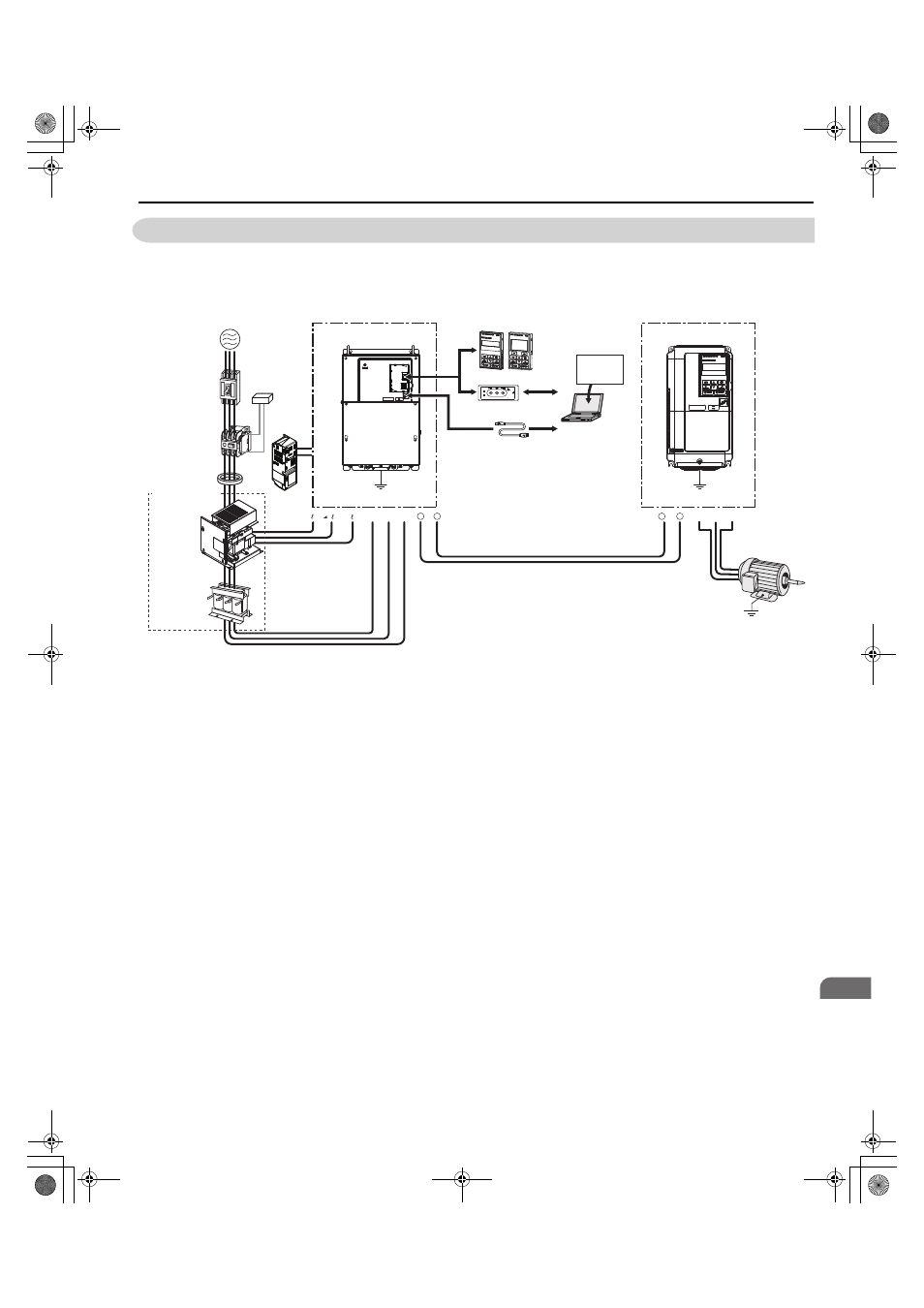
illustrates how to configure the converter with standard configuration devices, peripheral devices, and options.
Refer to the specific manual for the devices shown below for more detailed installation instructions.
Note: Refer to
Standard Connection Diagram on page 48
for details on connecting standard configuration devices.
Figure 7.1
Figure 7.1 Connecting Standard Configuration Devices and Peripheral Devices
(Model 2A0030, 2A0130, 4A0030 to 4A0185)
Note: If the converter is set to trigger a fault output when the fault restart function is activated (L5-02 = 1), then a sequence to interrupt
power when a fault occurs will turn off the power to the converter while the converter attempts to restart. The default setting for
L5-02 is 0 (fault output active during restart).
<1> A corresponding input-side AC reactor and harmonic filter module that consider the saturation current and thermal factors are required for each
model of converter. Always install the specified devices.
Co
py
Ver
ify
Re
ad
LOCK
YA
S
K
A
W
A
JVOP-181
USB Copy Unit
COM
ERR
Motor
U/T1 V/T2 W/T3
Ground
r1/ 11
1/ 21 t1/ 31
Line Breaker
(MCCB)
or
Leakage
Breaker
Magnetic
Contactor
(MC)
Surge
Absorber
Input-side
AC Reactor
Zero-phase
Reactor
Harmonic
Filter
Module
Converter
Power
Supply
Ground
Drive
Ground
-
+
R/L1 S/L2
+ 1
-
T/L3
PC
USB
Copy Unit
USB Cable
(Type-AB, sold separately)
LED Operator/LCD Operator
USB Cable
(Type-AB)
Engineering
Software Tools
DriveWizard
Industrial
24V Power
Supply
Standard Configuration
Devices
<1>
YAI
TOEP_C710656_07C_2_0.book 167 ページ 2015年1月9日 金曜日 午後6時23分