Control circuit terminal block functions, Input terminals – Yaskawa D1000 Series Power Regenerative Converter User Manual
Page 76
3.9 Control Circuit Wiring
76
YASKAWA ELECTRIC TOEP C710656 07C YASKAWA Power Regenerative Converter - D1000 Instruction Manual
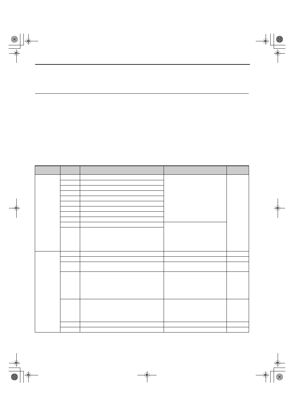
◆ Control Circuit Terminal Block Functions
Parameters determine which functions apply to the multi-function digital inputs (S1 to S8), multi-function relay outputs
(M1, M2, M3, M4, M5, M6), and multi-function analog monitor outputs (FM, AM). The default setting is listed next to
each terminal name in
.
NOTICE: Install an MC on the power supply side of the converter when the drive should not automatically restart after power loss. To
get the full performance life out of the electrolytic capacitors and circuit relays, refrain from switching the power supply off and on more
than once every 30 minutes. Frequent use can damage the converter.
■
Input Terminals
lists the input terminals on the converter. Text in parenthesis indicates the default setting for each multi-function
input.
Table 3.8 Control Circuit Input Terminals
<3> Set DIP switch S1 to select between a voltage or current input signal to terminal A2. The default setting is for current input. For
details, refer to
Terminal A2 Input Signal Selection on page 81
<4> Set DIP switch S2 to the ON position to enable the termination resistor in a MEMOBUS/Modbus network.
<5> Monitor outputs work with devices such as analog frequency meters, ammeters, voltmeters, and wattmeters. They are not intended
for use as a feedback-type signal.
Type
No.
Terminal Name (Function)
Function (Signal Level) Default
Setting
Page
Multi-Function
Digital Inputs
S1
Multi-function input 1 (RUN-SB)
• Photocoupler
• 24 Vdc, 8 mA
• Set the S3 jumper to select between
sinking, sourcing mode, and the power
supply. Refer to
.
S2
Multi-function input 2 (STOP)
S3
Multi-function input 3 (External fault)
S4
Multi-function input 4 (Fault reset)
S5
Multi-function input 5 (Reserved)
S6
Multi-function input 6 (Reserved)
S7
Multi-function input 7 (Reserved)
S8
Multi-function input 8 (External Baseblock)
SC
Multi-function input common
SP
Digital input power supply +24 Vdc
24 Vdc power supply for digital inputs,
150 mA max (only when not using digital
input option DI-A3)
NOTICE: Do not jumper or short
terminals SP and SN. Failure to
comply will damage the converter.
SN
Digital input power supply 0 V
Analog Inputs
+V
Analog reference input
10.5 Vdc (max allowable current 20 mA)
–
-V
Analog reference input
-10.5 Vdc (max allowable current 20 mA)
–
A1
Multi-function analog input 1 (Reserved)
-10 to 10 Vdc, 0 to 10 Vdc (input
impedance: 20 k
Ω)
A2
Multi-function analog input 2 (Reserved)
• -10 to 10 Vdc, 0 to 10 Vdc (input
impedance: 20 k
Ω)
• 4 to 20 mA, 0 to 20 mA (input
impedance: 250
Ω)
• Voltage or current input must be
selected by DIP switch S1 and H3-09.
A3
Multi-function analog input 3 (Reserved)
• -10 to 10 Vdc, 0 to 10 Vdc (input
impedance: 20 k
Ω)
• Use DIP switch S4 on the terminal
board to select between analog and PTC
input.
AC
Frequency reference common
0 V
–
E (G)
Ground for shielded lines and option cards
–
–
TOEP_C710656_07C_2_0.book 76 ページ 2015年1月9日 金曜日 午後6時23分