Yaskawa D1000 Series Power Regenerative Converter User Manual
Page 126
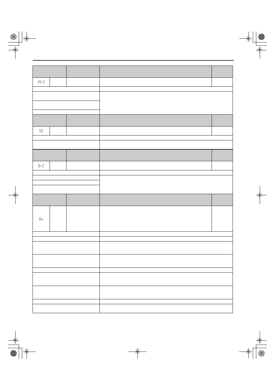
5.4 Alarm Detection
126
YASKAWA ELECTRIC TOEP C710656 07C YASKAWA Power Regenerative Converter - D1000 Instruction Manual
Digital Operator
Display
Minor Fault Name
Detail
Alarm
Output
(H2-=10)
PF3
Input Phase Loss
Detection
Abnormal oscillation continued in the input power supply voltage. (Detected
when L8-69 = 1.)
YES
Cause
Possible Solutions
The fluctuation in the voltage of the input
power supply is too large.
Investigate the cause and implement countermeasures.
Refer to
Diagnosing and Resetting Faults on page 131
A phase loss occurred in the input power
supply.
The interphase voltage balance is bad.
Digital Operator
Display
Minor Fault Name
Detail
Alarm
Output
(H2-=10)
SE
MEMOBUS/Modbus
Test Mode Fault
A MEMOBUS/Modbus communications test was performed during operation.
YES
Cause
Possible Solutions
A fault occurred during MEMOBUS/Modbus
Communications Test Mode.
Always stop the operation of the converter before you perform MEMOBUS/Modbus
communications tests.
Digital Operator
Display
Minor Fault Name
Detail
Alarm
Output
(H2-=10)
SrC
Phase Order Fault
The phase order detection direction for the input power supply changed after the
power supply was turned on.
YES
Cause
Possible Solutions
A momentary power loss occurred.
Investigate and correct the cause and reset the fault.
Refer to
Diagnosing and Resetting Faults on page 131
An input power supply wiring terminal is loose.
The fluctuation in the voltage of the input
power supply is too large.
Digital Operator
Display
Minor Fault Name
Detail
Alarm
Output
(H2-=10)
Uv
Undervoltage
One of the following conditions was true when the converter was stopped and a
Run command was entered:
• DC bus voltage dropped below the level specified in L2-05.
• Contactor to suppress inrush current in the converter was opened.
• Low voltage in the control converter input power. This alarm outputs only if
L2-01 is not 0 and DC bus voltage is under L2-05.
YES
Cause
Possible Solutions
Phase loss in the converter input power.
Check for wiring errors in the main circuit input power. Correct the wiring.
Loose wiring in the converter input power
terminals.
• Ensure the terminals have been properly tightened.
• Apply the tightening torque to the terminals as specified. Refer to
There is a problem with the converter input
power voltage.
• Check the voltage.
• Lower the voltage of the converter input power so that it is within the limits listed in the
specifications.
A power loss occurred.
Improve the power supply.
Internal circuitry is worn.
• Check the maintenance time for the capacitors (U4-05).
• Replace either the control board or the entire converter if U4-05 exceeds 90%. For instructions
on replacing the control board, contact Yaskawa or your nearest sales representative.
The converter input power transformer is too
small and voltage drops when the power is
switched on.
• Check for an alarm when the magnetic contactor, line breaker, and leakage breaker are closed.
• Check the capacity of the converter input power transformer.
Air inside the converter is too hot.
Check the temperature inside the converter.
The CHARGE light is broken or disconnected.
Replace either the control board or the entire converter. For instructions on replacing the control
board, contact Yaskawa or your nearest sales representative.
TOEP_C710656_07C_2_0.book 126 ページ 2015年1月9日 金曜日 午後6時23分