3 the drive and programming modes, The drive and programming modes, Drive mode details – Yaskawa D1000 Series Power Regenerative Converter User Manual
Page 90
90
YASKAWA ELECTRIC TOEP C710656 07C YASKAWA Power Regenerative Converter - D1000 Instruction Manual
4.3 The Drive and Programming Modes
4.3 The Drive and Programming Modes
The converter has a Drive Mode and a Programming Mode.
Drive Mode: In Drive Mode the user can operate the converter, monitor operating status (DC bus voltage, DC current
reference, etc.), and change the setting of d8-01. For details, refer to
Programming Mode: In Programming Mode the user can edit and verify parameter settings. When the converter is in
Programming Mode it will not accept a Run command unless b1-08 is set to 1.
◆ Navigating the Drive and Programming Modes (Default Setting)
NOTICE: Check the following items before you turn on the power supply.
• Is the power supply voltage correct?
200 V Class: 200 to 240 Vac 50/60 Hz
400 V Class: 380 to 480 Vac 50/60 Hz
• Are the converter and the control devices connected properly (e.g., is the phase order correct)?
• Is the phase order correct between the main circuit terminals (R/L1, S/L2, and T/L3) on the converter and
the power supply voltage detection terminals (r1/ 11, 1/ 21, and t1/ 31).
• Are the control circuit terminals on the converter connected properly to the control devices?
• Are the Run Commands for the converter and the control devices turned off?
The converter is set to operate in Drive Mode when it is first powered up. Switch between display screens by using the
and
keys.
■
Drive Mode Details
The following actions are possible in the Drive Mode:
• Run and stop the converter
• Monitor the operation status of the converter (DC bus voltage feedback, Power supply side voltage, Power supply side
current, etc.)
• View information on an alarm
• View a history of alarms that have occurred
Note: The converter must be in Drive Mode to operate. Change to another mode when the converter is stopped.
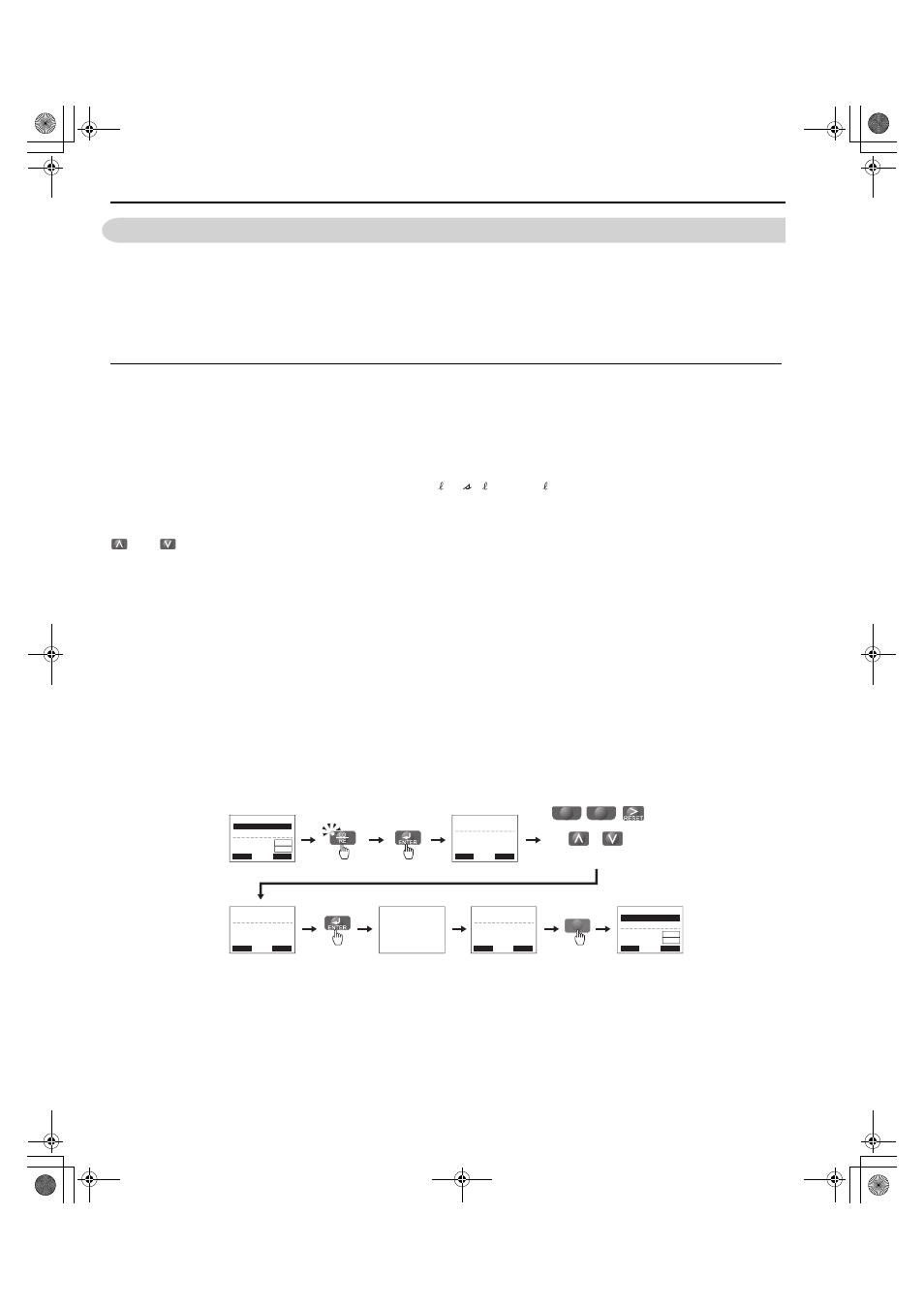
illustrates how to change the Output Voltage Reference from 600 (600 V) to 700 (700 V) while in the Drive
Mode.
This example assumes the converter is set to LOCAL.
Figure 4.2
Figure 4.3 Setting the DC Bus Voltage Reference while in the Drive Mode
Note: The converter will not accept a change to the value of DC bus voltage reference until the ENTER key is pressed after the value of
DC bus voltage reference is entered. This feature prevents accidental setting of the value of DC bus voltage reference.
ESC
F1
F2
←
→
←
→
←
→
DC bus voltage reference
display at power up
Press to select LOCAL
Press until the DC bus voltage
reference changes to 700V
left
right
- MODE -
U1-51= 600V
U1-52= 600V
U1-53= 0.00A
DRV
Volt Ref (OPR)
Rdy
RSEQ
LREF
- MODE -
U1-51= 700V
U1-52= 6000V
U1-53= 0.00A
DRV
Volt Ref (OPR)
Rdy
RSEQ
LREF
-MONITR-
Volt Ref (d8-01)
U1-51= 600V
(600
㨪730)
̌660V̍
DRV Rdy
-MONITR-
Volt Ref (d8-01)
U1-51= 700V
㧔600㨪730㧕
̌660V̍
DRV Rdy
-MONITR-
Volt Ref (d8-01)
U1-51= 700V
㧔600㨪730㧕
̌660V̍
DRV Rdy
Entry Accepted
YAI
TOEP_C710656_07C_2_0.book 90 ページ 2015年1月9日 金曜日 午後6時23分