5 operation with the drive connected, A1000 connection example, Refer to – Yaskawa D1000 Series Power Regenerative Converter User Manual
Page 95: A1000, Operation with the drive connected, Interlock with the drive on page 97
4.5 Operation with the Drive Connected
YASKAWA ELECTRIC TOEP C710656 07C YASKAWA Power Regenerative Converter - D1000 Instruction Manual
95
S
ta
rt
-Up Pr
ogr
amming
&
O
p
er
at
io
n
4
4.5 Operation with the Drive Connected
NOTICE: When installing a noise filter on the converter power supply, use a reactor-type noise filter (without a capacitor), such as a
zero phase reactor, and install it after the MCCB on the power supply side. Do not install a filter with a built-in capacitor as the harmonic
components may cause the capacitor to overheat or may damage the capacitor.
NOTICE: When installing a breaker or contactor on the converter side for an emergency shutoff, confirm that the CHARGE indicators
on the drive and converter are not lit before closing the breaker or contactor on the converter output (DC) side. If the power supply is
turned on while there is a voltage charge, an overcurrent will flow and the device may be damaged. Always confirm that the breaker or
contactor on the converter output (DC) side is turned on before applying power to the converter.
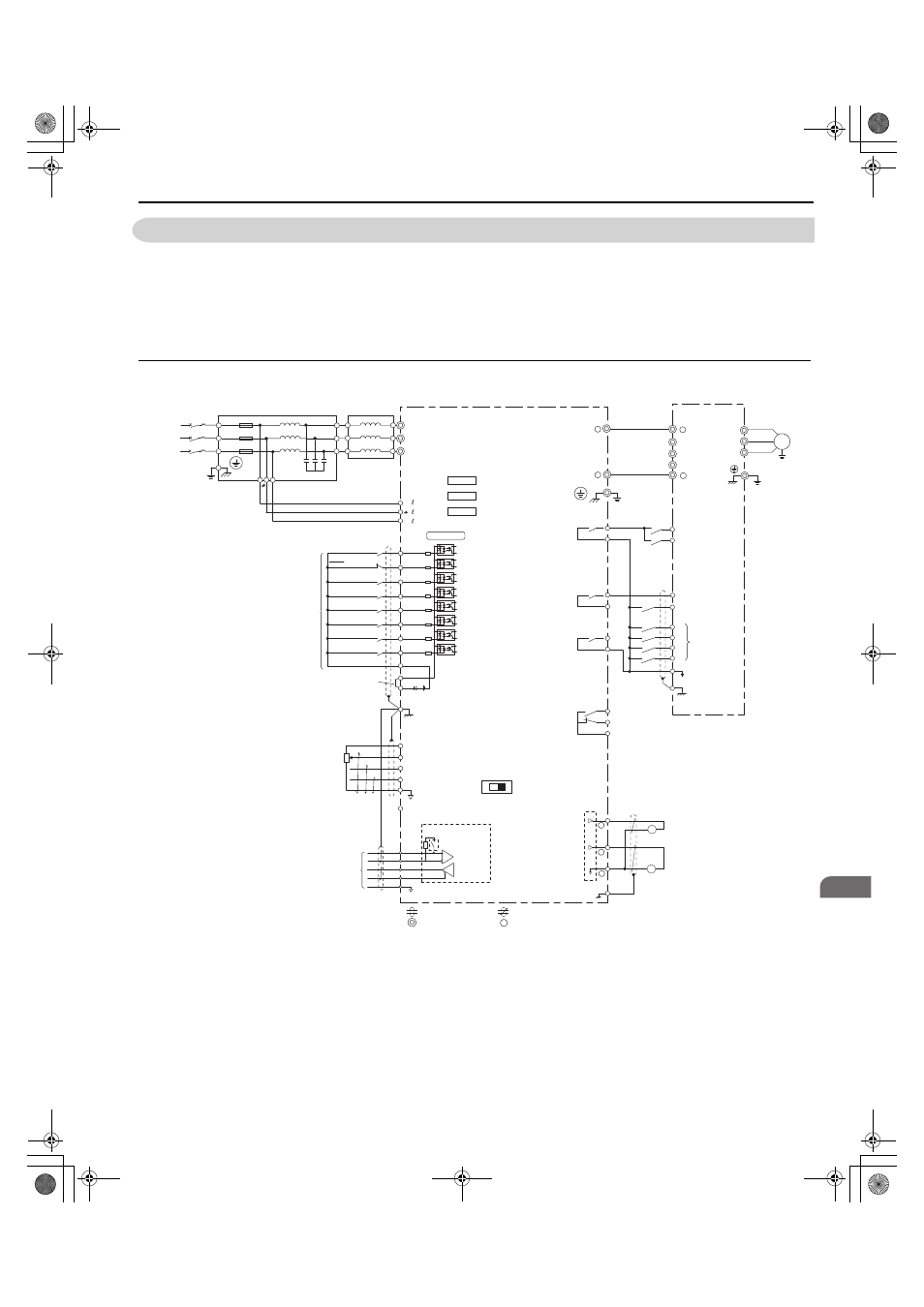
◆ A1000 Connection Example
Figure 4.3
Figure 4.4 Standard Connection Diagram with A1000 (Example for CIMR-D2A0030, 2A0130, and 4A0030 to 4A0185)
<1> Do not use a line longer than 10 m (32.8 ft) to connect the input-side AC reactor and the converter.
<2> Use the specified AC reactor and harmonic filter module. Non-specified devices may cause erroneous operation.
<3> Do not use a DC bus line that is longer than 5 m (16.4 ft) to connect the converter and drive.
<4> Sequence the operation so that the converter starts operation before the drive when power is applied. Sequence the stopping
operation to turn off the drive first, then the motor, and finally the converter. Operating the drive without operating the converter or
turning off the power supply unit during operation may trigger a converter fault.
<5> Do not connect a power supply to the drive AC power supply terminals (R/L1, S/L2, and T/L3).
<6> The connections are shown for sequence connections with no-voltage contacts or NPN transistors for the sequence input signals
(S1 to S8). Use jumper S3 to select between Sink mode and Source mode. The default setting is Sink mode.
<7> For information on an interlock with the drive, refer to
Interlock with the Drive on page 97
.
D1000
+
-
E(G)
MA
MB
MC
(Reserved)
(Reserved)
(Reserved)
Shield ground terminal
Converter
Fault relay output
250 Vac, max. 1 A
30 Vdc, max. 1 A
(min. 5 Vdc, 10 mA)
+V
A1
A2
A3
AC
R+
R-
S+
S-
IG
V
I
MEMOBUS/
Modbus Communication
RS-422/RS-485
max. 115.2 kbps
Control Circuit
-V
Power supply
+10.5 Vdc, max. 20 mA
Power supply, -10.5 Vdc,
max. 20 mA
Analog Input 1
Analog Input 2
Analog Input 3
DIP Switch S1
Multi-function relay output
(During MC on)
250 Vac, max. 1 A
30 Vdc, max. 1 A
(min. 5 Vdc, 10 mA)
Multi-function relay output
(Operation Ready)
250 Vac, max. 1 A
30 Vdc, max. 1 A
(min. 5 Vdc, 10 mA)
Multi-function relay
output (During Run 1)
<4>
250 Vac, max. 1 A
30 Vdc, max. 1 A
(min. 5 Vdc, 10 mA)
R/L1
S/L2
T/L3
CN5-A
CN5-B
CN5-C
Option card
connectors
S1 Forward Run / Stop
S2 Reverse Run / Stop
S3 External fault
S4 Fault reset
S5
S6
S7
S8
SC
Sequence common
Multi-function
digital inputs
Shield ground terminal
E(G)
A1000
Drive
+
R/L1
1
S/L2
T/L3
-
IM
U/T1
V/T2
W/T3
Ground
Motor
r1/ 11
1/ 21
t1/ 31
Ground
Three-
Phase
Power
Supply
Input-side AC
Harmonic Filter Module
U
V
W
X
Y
Z
GFCI
or
MCCB
X
Y
Z
R/L1
S/L2
T/L3
r
t
<1><2>
<2>
<3>
<5>
<7>
<3>
Termination resistor
(120 Ω, 1/2 W)
DIP Switch S2
M1
M2
M3
M4
M5
M6
S1
S2
S3
S4
S5
S6
S7
S8
SC
<6>
+24 V
RUN-SB
STOP
External fault
Fault reset
(Reserved)
(Reserved)
External Baseblock
(Reserved)
Multi-function
digital inputs
(default setting)
Sink / Source mode
selection wire link
(default: Sink)
SP
SN
0 V
FM
AM
AC
E (G)
Multi-function analog
output 1
(Output frequency)
-10 to +10 Vdc (2 mA) or
4 to 20 mA
Multi-function analog
output 2
(Output current)
-10 to +10 Vdc (2 mA) or
4 to 20 mA
FM
AM
shielded line
twisted-pair shielded line
main circuit terminal
control circuit terminal
-
+
-
YAI
TOEP_C710656_07C_2_0.book 95 ページ 2015年1月9日 金曜日 午後6時23分