2 standard connection diagram – Yaskawa D1000 Series Power Regenerative Converter User Manual
Page 51
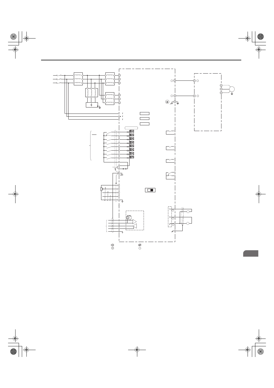
3.2 Standard Connection Diagram
YASKAWA ELECTRIC TOEP C710656 07C YASKAWA Power Regenerative Converter - D1000 Instruction Manual
51
El
ec
tr
ical
I
n
st
al
lat
ion
3
Figure 3.3
Figure 3.3 Standard Connection Diagram (example: model 4A0630)
<1> Do not use a line longer than 10 m (32.8 ft) to connect the input-side AC reactor and the converter.
<2> Use the specified AC reactor and harmonic filter module. Non-specified devices may cause erroneous operation.
<3> Do not use a DC bus line that is longer than 5 m (16.4 ft) to connect the converter and drive.
<4> Sequence the operation so that the converter starts operation before the drive when power is applied. Sequence the stopping
operation to turn off the drive first, then the motor, and finally the converter. Operating the drive without operating the converter or
turning off the power supply unit during operation may trigger a converter fault.
<5> Do not connect a power supply to the drive AC power supply terminals (R/L1, S/L2, and T/L3).
<6> The connections are shown for sequence connections with no-voltage contacts or NPN transistors for the sequence input signals
(S1 to S8). Use jumper S3 to select between Sink mode and Source mode. The default setting is Sink mode.
<7> Multi-function analog outputs work with devices such as analog frequency meters, ammeters, voltmeters, and wattmeters. They are
not intended for use as a feedback-type signal.
IM
D1000
+
-
r1/ 11
1/ 21
t1/ 31
S1
S2
S3
S4
S5
S6
S7
S8
E(G)
+
1
-
+V
A1
A2
A3
AC
(Reserved)
(Reserved)
(Reserved)
-V
Analog Input 1
Analog Input 2
Analog Input 3
R/L1
S/L2
T/L3
CN5-A
CN5-B
CN5-C
U
V
W
X
Y
Z
U
V
W
X
Y
Z
U
V
W
X
Y
Z
U
V
W
E
U
V
W
X
Y
Z
R1/L11
S1/L21
T1/L31
V
I
R+
R-
S+
S-
IG
<5>
<1><2>
<2>
<2>
<3>
<3>
Three-
Phase
Power
Supply
GFCI
or
MCCB
Input-side AC
reactor 1
Input-side
AC reactor 1
Input-side AC
reactor 2
Converter
Option card
connectors
Control Circuit
Shield ground terminal
Sink
Power supply
+10.5 Vdc, max. 20 mA
MEMOBUS/
Modbus Communication
RS-422/RS-485
max. 115.2 kbps
Termination resistor
(120
Ω, 1/2 W)
DIP
Switch S2
DIP Switch S1
Ground
Drive
Motor
Reactor for
harmonic filter
Capacitor for
harmonic filter
Power supply, -10.5 Vdc,
max. 20 mA
RUN-SB
External fault
Fault reset
(Reserved)
(Reserved)
(Reserved)
External
Baseblock
STOP
Multi-function
digital inputs
(default setting)
shielded line
twisted-pair shielded line
main circuit terminal
control circuit terminal
MA
MB
MC
Fault relay output
250 Vac, max. 1 A
30 Vdc, max. 1 A
(min. 5 Vdc, 10 mA)
Multi-function relay output
(During MC on)
250 Vac, max. 1 A
30 Vdc, max. 1 A
(min. 5 Vdc, 10 mA)
Multi-function relay output
(Operation Ready)
250 Vac, max. 1 A
30 Vdc, max. 1 A
(min. 5 Vdc, 10 mA)
Multi-function relay
output (During Run 1)
<4>
250 Vac, max. 1 A
30 Vdc, max. 1 A
(min. 5 Vdc, 10 mA)
M1
M2
M3
M4
M5
M6
0 V
FM
AM
AC
E (G)
<7>
<7>
Multi-function analog
output 1
(Output frequency)
-10 to +10 Vdc (2 mA) or
4 to 20 mA
Multi-function analog
output 2
(Output current)
-10 to +10 Vdc (2 mA) or
4 to 20 mA
FM
AM
SC
+24 V
Sink / Source mode
selection wire link
(default: Sink)
SP
SN
<6>
+
-
-
YAI
TOEP_C710656_07C_2_0.book 51 ページ 2015年1月9日 金曜日 午後6時23分