4 powering up the converter, Powering up the converter, Status display – Yaskawa D1000 Series Power Regenerative Converter User Manual
Page 94
94
YASKAWA ELECTRIC TOEP C710656 07C YASKAWA Power Regenerative Converter - D1000 Instruction Manual
4.4 Powering Up the Converter
4.4 Powering Up the Converter
◆ Powering Up the Converter and Operation Status Display
■
Powering Up the Converter
Review the following checklist before turning the power on.
NOTICE: Equipment Damage. Check the following items before you turn on the power supply. Failure to comply could result in damage
to the converter and harmonic filter module.
■
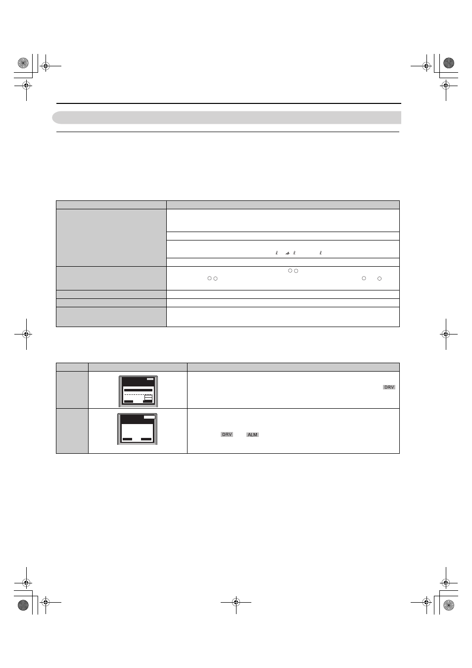
Status Display
When the power supply to the converter is turned on, the digital operator lights will appear as follows:
Item to Check
Description
Power supply voltage
Check the power supply voltage.
200 V class: Three-phase 200 to 240 Vac 50/60 Hz
400 V class: Three-phase 380 to 480 Vac 50/60 Hz
Properly wire the power supply input terminals (R/L1, S/L2, and T/L3).
Properly wire the phase order of the power supply input terminals (R/L1, S/L2, and T/L3) and the
power supply voltage detection terminals (
).
Check for proper grounding of converter.
Converter output terminals and drive
terminals
Properly connect the DC voltage output terminals ( / ) on the converter to the DC power supply
input terminals ( / ) on the drive. Be particularly careful to correctly connect the and
terminals.
Control circuit terminals
Properly connect the control circuit terminals on the converter to other control devices.
Converter control terminal status
Turn off the Run Commands for the converter and the peripheral control devices.
Input-side AC reactor and harmonic
filter (harmonic filter module)
connections to converter
Properly connect the AC reactor and harmonic filter (harmonic filter module) to converter as
shown in the Standard Connection Diagram.
Status
Name
Description
Normal
Operation
The data display area displays the DC bus voltage reference DC voltage feedback.
is lit.
Fault
Example: External Fault
Data displayed varies by the type of fault. Refer to
information.
and
are
lit.
r1/ 11, 1/ 21, and t1/ 31
+ –
+ –
+
–
DIGITAL OPERATOR JVOP-180
ALARM
- MODE -
U1-51= 330V
U1-52= 330V
U1-53= 0.00A
DRV
Volt Ref (OPR)
Rdy
RSEQ
LREF
YAI
DIGITAL OPERATOR JVOP-180
ALARM
- MODE -
EF3
Ext Fault S3
DRV
RESET
YAI
TOEP_C710656_07C_2_0.book 94 ページ 2015年1月9日 金曜日 午後6時23分