Yaskawa CIMR-LU Drives User Manual
Page 211
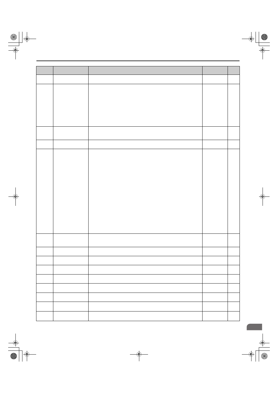
B Parameter Table
YASKAWA ELECTRIC TOEP C710616 38F YASKAWA AC Drive L1000A Quick Start Guide
211
Par
ame
te
r Ta
ble
B
U4-17
Drive Overload
Calculations (OL2)
Displays the level of the drive overload detection (oL2). A value of 100% is equal
to the oL2 detection level.
10 V = 100%
0.1%
U4-18
Speed Reference
Selection Results
Displays the source for the speed reference as XY-nn.
X: indicates which reference is used:
1 = Reference 1 (b1-01)
Y-nn: indicates the reference source
0-01 = Digital operator
1-01 = Analog (terminal A1)
1-02 = Analog (terminal A2)
2-02 to 8 = Digital Inputs (d1-02 to 8)
3-01 = MEMOBUS/Modbus communications
4-01 = Communication option card
No signal output
available
–
U4-19
Speed Reference from
MEMOBUS/Modbus
Comm.
Displays the speed reference provided by MEMOBUS/Modbus (decimal).
No signal output
available
0.01%
U4-20
Speed Reference From
Option Card
Displays the speed reference input by an option card (decimal).
No signal output
available
0.01%
U4-21
Up/Down Command
Source Selection
Displays the source for the Up/Down command as XY-nn.
X: Indicates which Up/Down command source is used:
1 = Reference 1 (b1-02)
Y: Input power supply data
0 = Digital operator
1 = External terminals
3 = MEMOBUS/Modbus communications
4 = Communication option card
nn: Up/Down command limit status data
00: No limit status.
01: Up/Down command was left on when stopped in the PRG mode
02: Up/Down command was left on when switching from LOCAL to REMOTE
operation
03: Waiting for soft charge bypass contactor after power up (Uv or Uv1 flashes
after 10 s)
04: Waiting for "Up/Down Command Prohibited" time period to end
05: Fast Stop (multi-function input, operator)
07: During baseblock while coast to stop with timer
08: Speed reference is below minimal reference during baseblock
09: Waiting for Enter command
No signal output
available
–
U4-22
MEMOBUS/Modbus
Communications
Reference
Displays the drive control data set by MEMOBUS/Modbus communications
register no. 0001H as a four-digit hexadecimal number.
No signal output
available
–
U4-23
Communication Option
Card Reference
Displays drive control data set by an option card as a four-digit hexadecimal
number.
No signal output
available
–
U4-24
Number of Travels
(Lower 4 digit)
Displays the lower four digits for the number of trips the drive has made.
No signal output
available
1 time
U4-25
Number of Travels
(Higher 4 digit)
Displays the upper four digits for the number of trips the drive has made.
No signal output
available
1 time
U4-26
Max. Current during
Acceleration
Shows the maximum current that occurred during acceleration.
No signal output
available
0.1 A
U4-27
Max. Current during
Deceleration
Shows the maximum current that occurred during deceleration.
No signal output
available
0.1 A
U4-28
Max. Current during
Constant Speed
Shows the maximum current that occurred during ride at top speed.
No signal output
available
0.1 A
U4-29
Max. Current during
Leveling Speed
Shows the maximum current that occurred during ride at leveling speed.
No signal output
available
0.1 A
U4-30
Slip Compensation
Value
Shows the slip compensation value.
No signal output
available
0.01%
No.
Name
Description
Analog Output
Level
Unit
TOEP_C710616_38F_5_0.book 211 ページ 2013年12月4日 水曜日 午前9時56分