L: protection functions, L1: motor protection, L2: undervoltage detection – Yaskawa CIMR-LU Drives User Manual
Page 189
B Parameter Table
YASKAWA ELECTRIC TOEP C710616 38F YASKAWA AC Drive L1000A Quick Start Guide
189
Par
ame
te
r Ta
ble
B
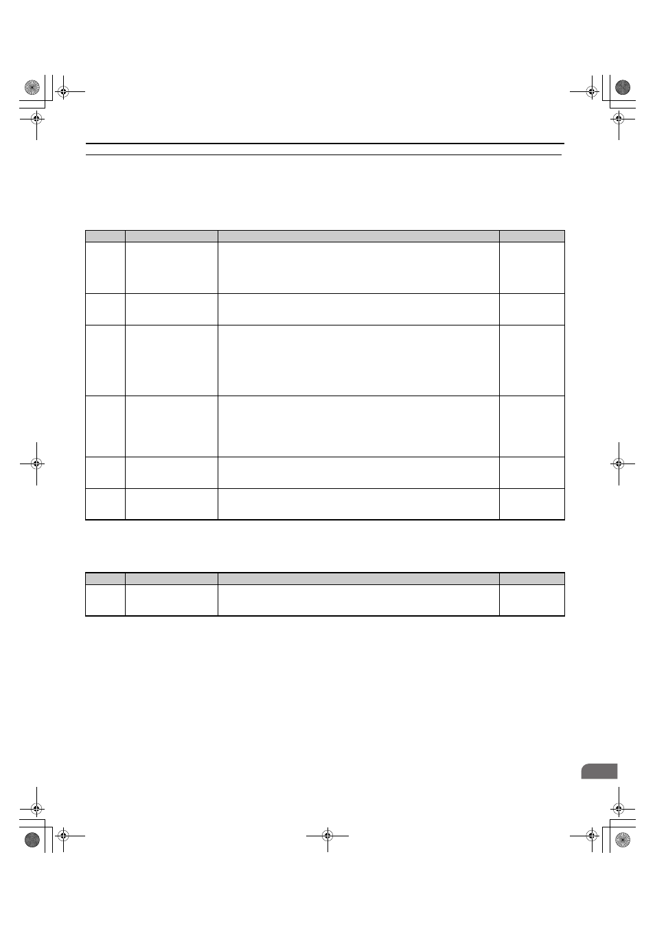
◆ L: Protection Functions
L parameters provide protection to the drive and motor, including control during momentary power loss, Stall Prevention,
frequency detection, fault reset, overtorque detection, torque limits, and other types of hardware protection.
■
L1: Motor Protection
■
L2: Undervoltage Detection
No.
Name
Description
Setting
L1-01
<5> Default setting is determined by the control mode (A1-02).
<44> Available in drive software versions PRG: 7017 or later.
Motor Overload Protection
Selection
0: Disabled
1: General purpose motor (standard fan cooled)
2: Drive dedicated motor with a speed range of 1:10
3: Vector motor with a speed range of 1:100
5: PM motor with constant torque characteristics
Min: 0
Max: 5
L1-02
Motor Overload Protection
Time
Sets the motor thermal overload protection (oL1) time.
Default: 1.0 min
Min: 0.1 min
Max: 5.0 min
L1-03
Motor Overheat Alarm
Operation Selection (PTC
thermistor input)
Sets operation when the motor temperature analog input (H3-02 or H3-10 = E)
exceeds the oH3 alarm level.
0: Ramp to stop
1: Coast to stop
2: Emergency Stop (Fast Stop) (decelerate to stop using the deceleration time in C1-
09)
3: Alarm only (“oH3” will flash)
Default: 3
Min: 0
Max: 3
L1-04
Motor Overheat Fault
Operation Selection (PTC
thermistor input)
Sets stopping method when the motor temperature analog input (H3-02 or H3-10 = E)
exceeds the oH4 fault level.
0: Ramp to stop
1: Coast to stop
2: Emergency Stop (Fast Stop) (decelerate to stop using the deceleration time in C1-
09)
Default: 1
Min: 0
Max: 2
L1-05
Motor Temperature Input
Filter Time (PTC
thermistor input)
Adjusts the filter for the motor temperature analog input (H3-02 or H3-10 = E).
Default: 0.20 s
Min: 0.00 s
Max: 10.00 s
L1-13
Continuous Electrothermal
Operation Selection
0: Disabled
1: Enabled
Default: 1
Min: 0
Max: 1
No.
Name
Description
Setting
L2-05
<9> Values shown here are for 200 V class drives. Double the value when using a 400 V class drive. Multiply value by 2.875 for 600 V class drives.
<15> Default setting value is dependent on the setting for the input voltage (E1-01).
Undervoltage Detection
Level (Uv)
Sets the DC bus undervoltage trip level.
Min: 150 Vdc
Max: 210 Vdc
TOEP_C710616_38F_5_0.book 189 ページ 2013年12月4日 水曜日 午前9時56分