Q3: output current limit, Q4: water level control – Yaskawa iQpump1000 AC Drive Quick Start User Manual
Page 391
No.
(Addr.
Hex)
Name
LCD Display
Description
Values
Page
Q2-09
(0E92)
Geothermal
Temperature Loss
Detection
Geotherm Loss Det
0: Disabled
1: Alarm Only
2: Fault
Selects the drive response when the signal from Terminal A2
falls below 3 mA or rises above 21 mA.
This parameter is only effective when H3-0o = 2 (4 to 20 mA)
and H3-0o = 21 (Geothermal Temperature).
0: Disabled
1: Alarm
2: Fault
Default: 1
Range: 0 to 2
–
Q2-10
(0E93) Geothermal Sleep Delay
Time
Geotherm Slp Dly
Set the length of time that the drive must be running at the speed
set in Q2-03, Minimum Geothermal Speed, before going to
sleep.
Default: 30 s
Min.: 0
Max.: 3600
–
Q2-11
(0E94)
Geothermal
Temperature Delta
Wake Level
Geotherm Wake Lvl
Sets the geothermal temperature that will wake up the drive.
The drive will wake up when one of the following conditions is
true:
Temperature > Q2-07 + Q2-11 OR
Temperature < Q2-06 - Q2-11
Setting this parameter to 0.0 will disable Geothermal Sleep
Mode.
Default: 0.0 °F
Min.: 0.0
Max.: 50.0
–
Q2-12
(0E95) Geothermal Sleep
Wake-Up Delay Time
Geotherm Wake Dly
Sets the length of time that the setting of Q2-11, Geothermal
Temperature Delta Wake Level, must be met to wake up the
drive.
Default: 5 s
Min.: 0
Max.: 3600
–
u
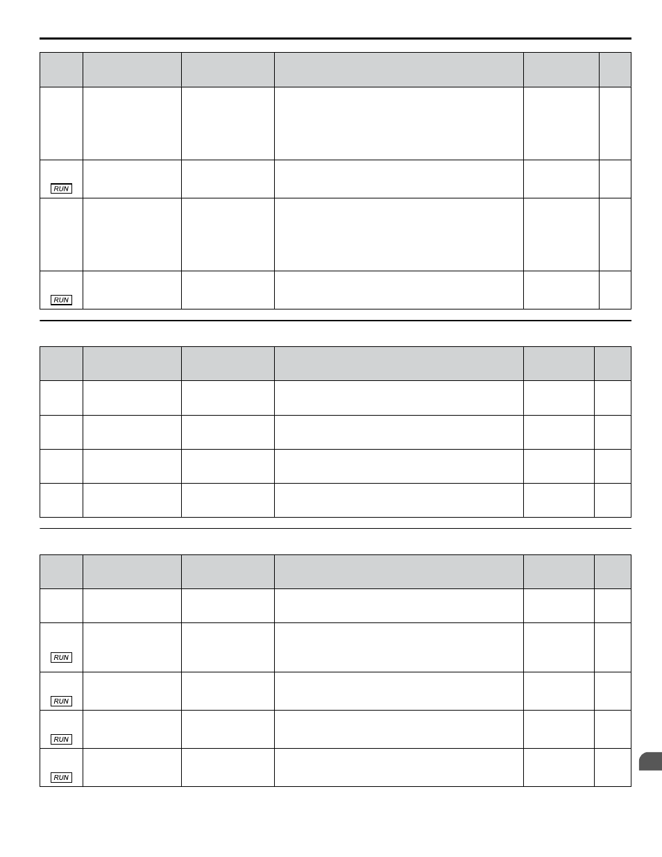
Q3: Output Current Limit
No.
(Addr.
Hex)
Name
LCD Display
Description
Values
Page
Q3-01
(0EBC)
Output Current Limit
Select
Current Lim Sel
0: Disabled
1: Enabled
Enables and disables the output current regulator.
0: Disabled
1: Enabled
Default: 0
Range: 0, 1
–
Q3-02
(0EBD) Current Limit
Current Limit
Sets the current limit. Value is internally limited to 300% of the
drive rated current.
Default: 0.0 A
Min.: 0.0
Max.: 1000.0
–
Q3-10
(0EC5)
Ripple Regulator
Selection
Ripple Reg Sel
0: Disabled
1: Enabled
Enables and disables the single phase ripple regulator.
0: Disabled
1: Enabled
Default: 1
Range: 0, 1
–
Q3-11
(0EC6)
Ripple Regulator
Setpoint
Ripple Reg S.P.
Set as a percentage of the maximum amount of ripple allowed
before triggering an input phase loss fault.
Default: 95.0%
Min.: 0.0
Max.: 200.0
–
u
Q4: Water Level Control
No.
(Addr.
Hex)
Name
LCD Display
Description
Values
Page
Q4-01
(0EEE) Water Level Selection
Water Level Sel
0: Disabled
1: Enabled
Enables and disables the water level control.
0: Disabled
1: Enabled
Default: 0
Range: 0, 1
–
Q4-02
(0EEF) Water Level Scaling
Water Lvl Scale
Sets the full scale (20 mA) output of the pressure transducer that
is connected to the analog input terminal programmed for
“WaterLvl/Suction” (H3-oo = 23).
Note:
1 PSI = 2.308 feet of water
Default: 100 PSI
Min.: 5
Max.: 500
–
Q4-03
(0EF0) Water Level Setpoint
Water Lvl Setpnt
Sets the amount of water above the sensor to which the drive
will attempt to regulate.
Default: 20.0 ft
Min.: 0.0
Max.: 1200.0
–
Q4-04
(0EF1) Minimum Water Level Min Water Level
Sets the level below which the amount of water must drop for
the time set in Q4-05 to put the drive to sleep.
Default: 10.0 ft
Min.: 0.0
Max.: 1200.0
–
Q4-05
(0EF2) Water Level Sleep
Delay Time
WL Sleep Dly Tm
Sets the length of time that the drive will delay after the water
level drops below the level set in Q4-04 before going to sleep.
Default: 5 s
Min.: 0
Max.: 3600
–
B.12 Q: PID Controller Parameters
YASKAWA TOEP YAIP1W 01B YASKAWA AC Drive - iQpump1000 Quick Start Guide
391
B
Parameter List