Multiplexing stop history – Yaskawa iQpump1000 AC Drive Quick Start User Manual
Page 204
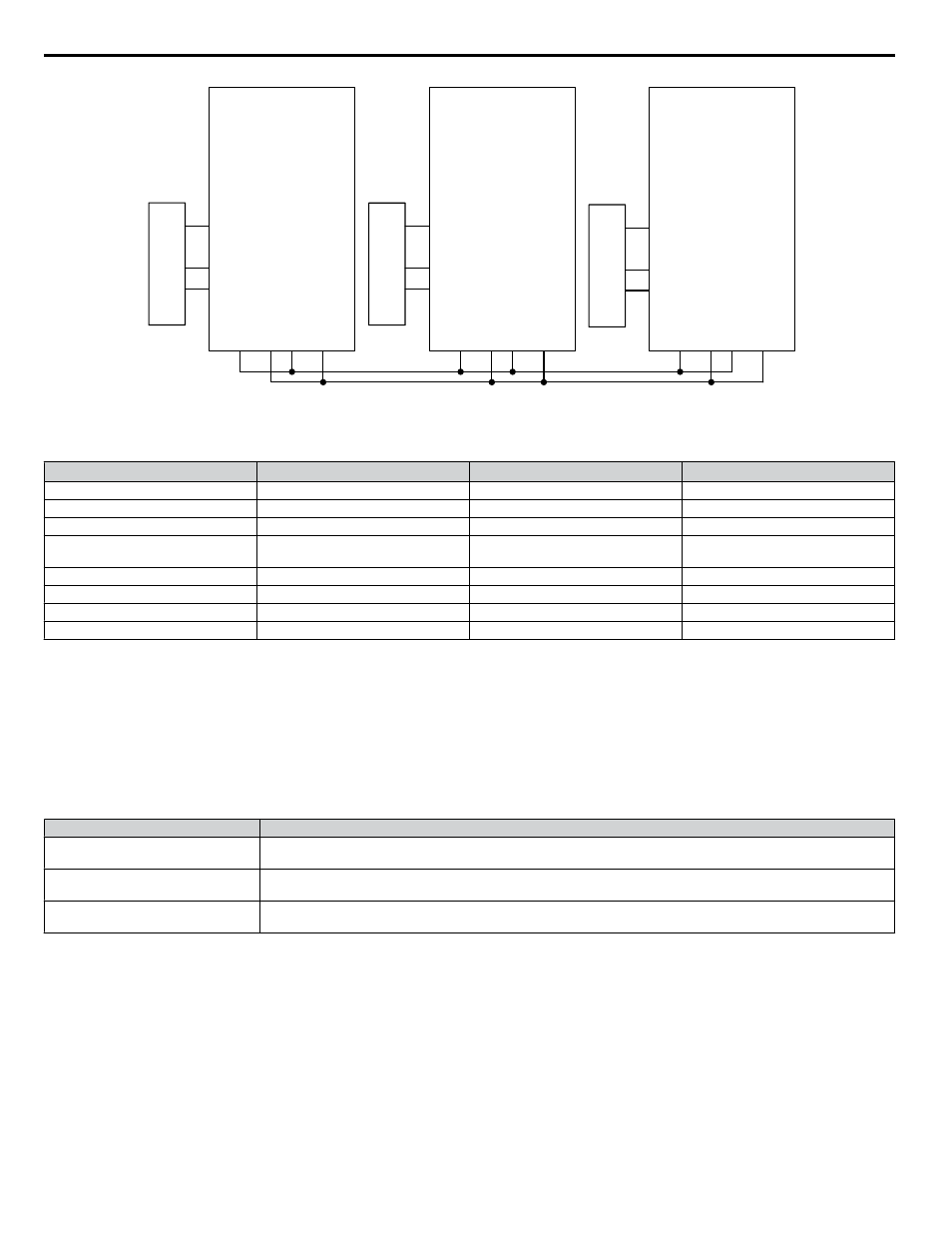
Drive A
25 HP
R+
S+
S-
R-
A2
AC
+V
A1
SN
S1
Drive B
25 HP
R+
S+
S-
R-
A2
AC
+V
A1
SN
S1
SYSTEM PRESSURE
FEEDBACK
Drive C
25 HP
R+
S+
S-
R-
A2
AC
+V
A1
SN
S1
SYSTEM PRESSURE
FEEDBACK
SYSTEM PRESSURE
FEEDBACK
Figure 4.25 Simplified Wiring Diagram
Table 4.13 Related Parameters for Triplex System Example
Description
Drive A
<1>
Drive B
<1>
Drive C
<1>
Node Address
H5-01 = 1
H5-01 = 2
H5-01 = 3
Highest Node Address
P9-25 = 3
P9-25 = 3
P9-25 = 3
Pump Mode: 3 (Network)
P1-01 = 3
P1-01 = 3
P1-01 = 3
Feedback Source: 2 (Analog ->Net,
with Alarm)
P9-02 = 2
P9-02 = 2
P9-02 = 2
Alternation Mode: 3 (FIFO @ Sleep)
P9-04 = 3
P9-04 = 3
P9-04 = 3
Maximum Running Pumps
P9-23 = 2
P9-23 = 2
P9-23 = 2
Setpoint
U5-99 = 90 PSI
U5-99 = 90 PSI
U5-99 = 90 PSI
Start Level
P1-04 = 75 PSI
P1-04 = 75 PSI
P1-04 = 75 PSI
<1> All other multiplexing and alternation parameters are set to default settings.
n
Multiplexing Stop History
Many irrigation-pumping skids consist of a PM pump (Pressure Maintenance) and typically two larger booster pumps to
maintain high flow peak demands. In many cases depending on the number of irrigation zones in combination with the type
of sprinkler heads used, the flow demand fluctuates and may not require the use of both larger booster pumps at the same time
until higher flow rates are required. The drive Controller "Run Stop" history ensures that both booster pumps alternate each
run cycle.
Table 4.14 P9-01, Lead Drive Selection, Detection Settings
Setting
Description
0
Next Available
Select next available drive on the network as the new lead drive
1
Lowest Runtime (default)
Select the iQpump Controller with the lowest runtime as the new lead drive
2
Stop History
Select the iQpump that had been stopped for the longest time.
Note:
The new lead drive selection also applies to Alternation (P9-03 > 0) and will use the Stop History list when finding the alternate.
Triplex Irrigation Booster System Example
When pressure is dropping, the PM Pump (if installed) will attempt to return the system pressure to the desired setpoint level.
If the PM Pump is not able to return the system to the setpoint pressure, typically due to a greater flow demand, the booster
pump #1 will be staged on.
The drive controller will speed up or slow down the pump as needed to maintain the system pressure. When flow decreases
and the pump system is no longer required to run, the system will go to sleep waiting for the pressure to drop. On the next run
cycle the PM pump will start up again, and instead of running booster pump #1, booster pump #2 is stages on, since booster
#1 ran during the last cycle.
This method ensures that during normal operation both booster pumps will operate evenly as lead or lag pumps each run cycle.
4.5 iQpump Presets and Functions
204
YASKAWA TOEP YAIP1W 01B YASKAWA AC Drive - iQpump1000 Quick Start Guide