Vertical turbine controller (vtc), Required control wiring, Drive 1 – Yaskawa iQpump1000 AC Drive Quick Start User Manual
Page 188
P9-07
Lag
Fixed
Delay
P9-07
Lag
Fixed
Delay
Drive 1
Drive 1
Drive 2
Drive 2
Drive 3
Drive 3
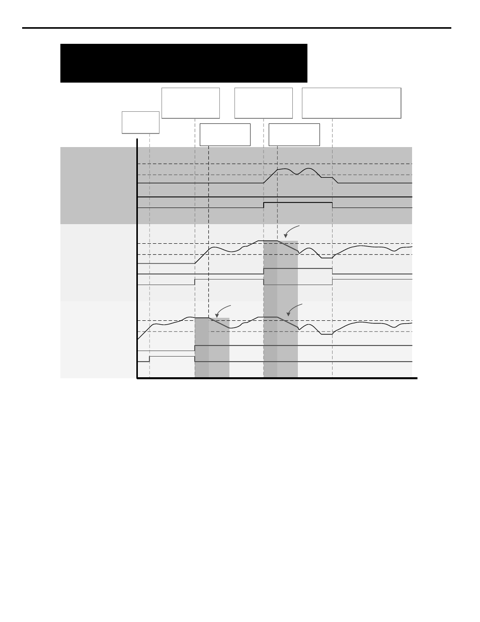
P9-01 = 1 (Lowest Run-time)
P9-08 = 0 (Output Frequency)
P9-32 = 60.0 sec
PumpNet Control1 U1-59 bit 1:
Run as Lag Drive
PumpNet Control1 U1-59 bit 2:
Run as Lead Drive
PumpNet Control1 U1-59 bit 1:
Run as Lag Drive
PumpNet Control1 U1-59 bit 2:
Run as Lead Drive
PumpNet Control1 U1-59 bit 1:
Run as Lag Driv
e
PumpNet Control1 U1-59 bit 2:
Run as Lead Drive
Drive 3 Staged-in.
Drive 2 becomes a Lag
Drive and latches to its
current output speed.
Drive 3 is no longer needed and gets de-
staged.
Drive 2 is the Lead again.
Drive 1 follows the speed of Drive 2 again.
Output Frequency
Output Frequency
Output Frequency
Output Frequency
Output Frequency
Output Frequency
Add Freq Level P9-09
Add Freq Level P9-09
Add Freq Level P9-09
Add Freq Level P9-09
Add Freq Level P9-09
Add Freq Level P9-09
Remove Freq Level P9-13
Remove Freq Level P9-13
Remove Freq Level P9-13
Remove Freq Level P9-13
Remove Freq Level P9-13
Remove Freq Level P9-13
Start-up…
Drive 1 is the
Lead Pump.
Drive 2 Staged-in.
Drive 1 becomes a Lag
Drive and latches to its
current output speed.
Drive 1 follows the
speed of Drive 2
(Lead)
Drive 1 and Drive 2
follows the speed of
Drive 3 (Lead)
P9-33
Lag
Followr
Dtim
P9-33
Lag
Followr
Dtim
P9-32
Lag Followr Dcel
P9-32
Lag Followr Dcel
P9-32
Lag Followr Dcel
P9-05 = 3 (Follow Lead Speed)
P9-12 = 0 (Output Frequency)
P9-33 = 10.0 sec
Figure 4.15 Lag Follower Deceleration Time Switching (Enabled)
n
Vertical Turbine Controller (VTC)
Vertical turbine pumps are typically used when water needs to be pumped from deep-water wells or open bodies of water such
as rivers, lakes, irrigation canals, lifting stations, and water storage facilities. The VTC Application Preset allows the operator
to easily setup control for a wide range of pumping applications. The drive will automatically adjust pump-operating conditions
from Simplex (one pump on the drive) to multiple lag pumps as the process variables change. Control can be extended from
simple pressure regulation to adding suction and vacuum control as well.
Required Control Wiring
Most pressure transducers have current-based feedback (4 - 20 mA). The drive A2 terminal is pre-set for 4-20 mA and pre-
programmed for PI feedback (H3-10 = B). If the sensor is voltage based (0-10 V) and terminal A3 is unused, then wire the
transducer to terminal A3 and program H3-10 to F (A2 not used) and H3-06 to B (A3 PI Feedback).
When using lag pumps, the lag pump on/off control must be wired to the drive digital output terminals. The figure below
shows the drive with the pressure transducer wired into terminal A2 and 3 lag pumps wired into output relays.
4.5 iQpump Presets and Functions
188
YASKAWA TOEP YAIP1W 01B YASKAWA AC Drive - iQpump1000 Quick Start Guide