Figure 3: ucm6510 t1/e1/j1 crossover cable pin-out – Grandstream UCM6510 User Manual User Manual
Page 27
Firmware Version 1.0.2.5
UCM6510 IP PBX User Manual
Page 26 of 313
1. Connect one end of an RJ-45 Ethernet cable (cable type: straight through) into the WAN port of the
UCM6510; connect the other end into the uplink port of an Ethernet switch/hub.
2. Connect the 12V DC power adapter into the DC 12V power jack 1 on the back of the UCM6510. Insert
the main plug of the power adapter into a surge-protected power outlet. (Connect the second power
adapter into the DC 12V power jack 2 for failover purpose in case the first one is down).
3. Wait for the UCM6510 to boot up. The LCD in the front will show its hardware information when the
bootup process is done.
4.
Once the UCM6510 is successfully connected to the network, the LED indicator for the WAN port in
the front will be in solid green and the LCD shows up the IP address.
Depending on how the UCM6510 is used, users can follow the steps below for optional setup:
1. PSTN Line Connection: connect PSTN lines from the wall jack to the UCM6510 LINE ports (FXO
ports).
2. Analog Line Connection: connect analog lines (phone and fax) to the PHONE ports (FXS ports).
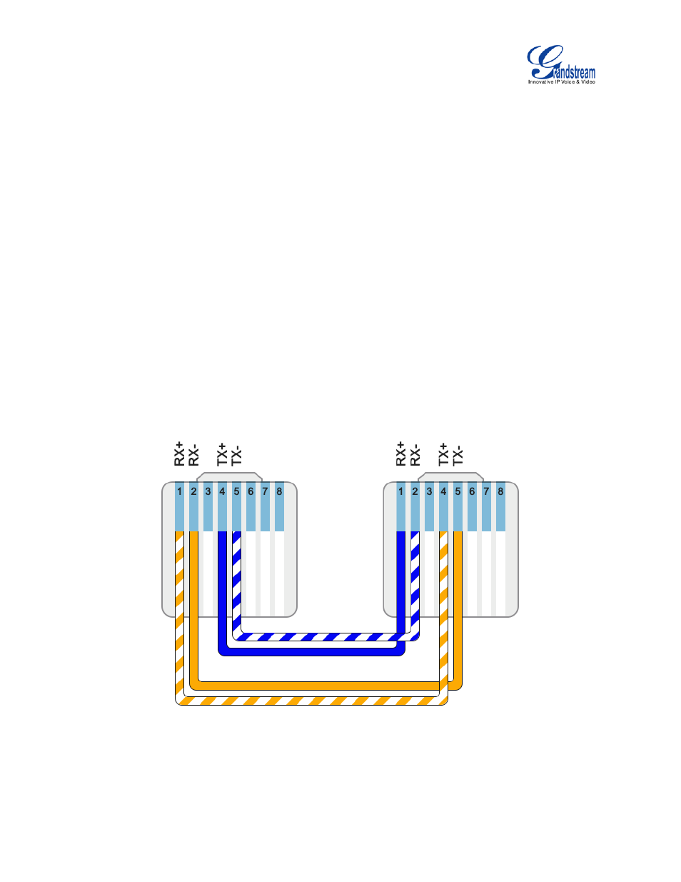
3. T1/E1/J1 Line Connection: connect one end of the T1/E1/J1 cable provided from the service provider
into the T1/E1/J1 port of the UCM6510; connect the other end into the T1/E1/J1 wall jack. T1/E1/J1
crossover cable should be used and it’s not provided in the UCM6510 package. Please see T1/E1/J1
crossover cable pin-out in the figure below:
Figure 3: UCM6510 T1/E1/J1 Crossover Cable Pin-out