Altera Arria V Avalon-ST User Manual
Page 123

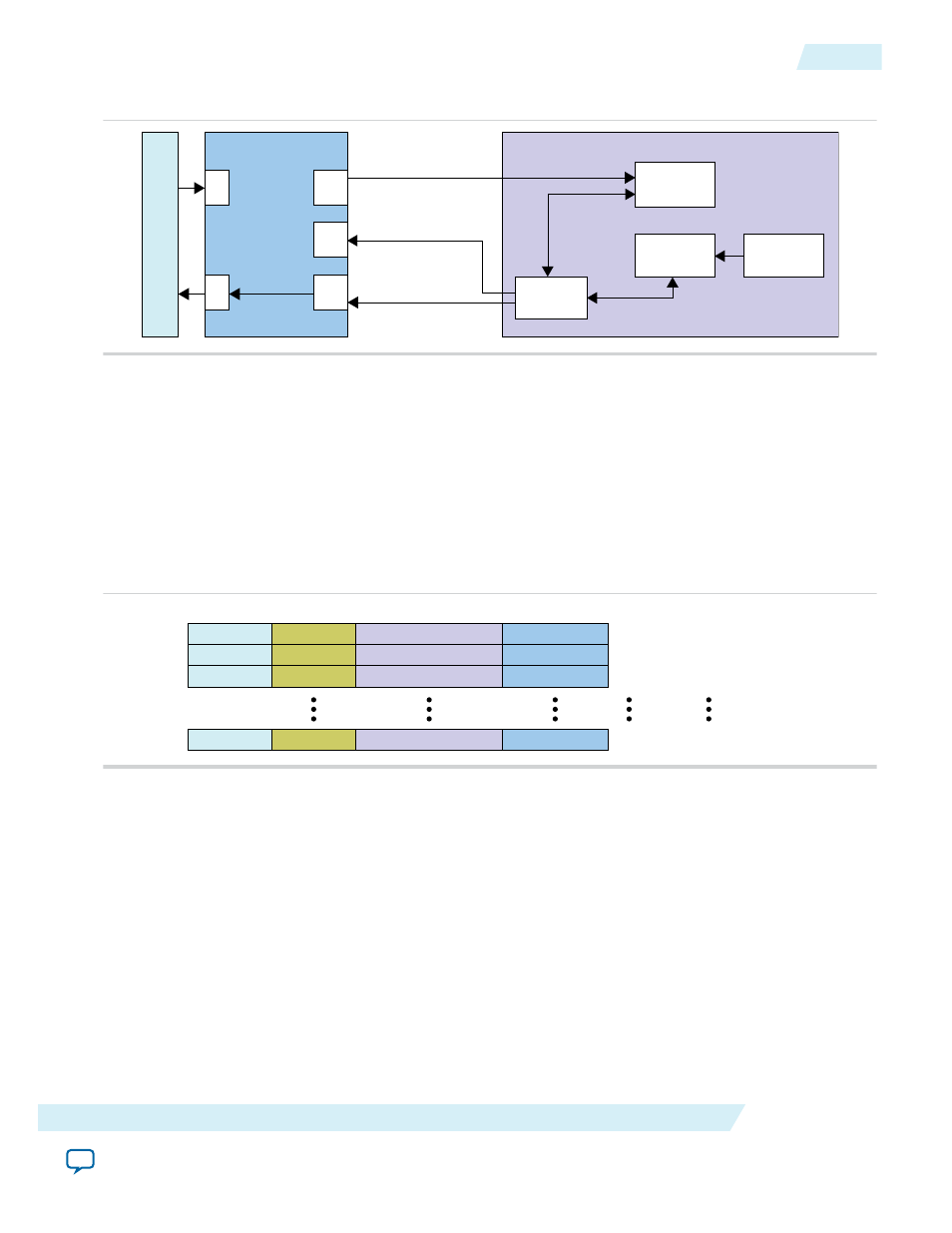
Figure 7-5: MSI-X Interrupt Components
Host
RX
TX
RX
TX
MSI-X
PCIe with Avalon-ST I/F
MSI-X Table
IRQ
Processor
MSI-X PBA
IRQ Source
Application Layer
Host SW Programs Addr,
Data and Vector Control
Memory Write
TLP
Memory Write TLP
Monitor & Clr
Addr, Data
App MSI-X Interface
1. Host software sets up the MSI-X interrupts in the Application Layer by completing the following steps:
a. Host software reads the
Message Control
register at 0x050 register to determine the MSI-X Table
size. The number of table entries is the
The maximum table size is 2048 entries. Each 16-byte entry is divided in 4 fields as shown in the
figure below. The MSI-X table can reside in any BAR. The base address of the MSI-X table must be
aligned to a 4 KByte boundary.
b. The host sets up the MSI-X table. It programs MSI-X address, data, and masks bits for each entry as
shown in the figure below.
Figure 7-6: Format of MSI-X Table
Vector Control
Vector Control
Vector Control
Vector Control
Message Data
Message Data
Message Data
Message Data
DWORD 3
DWORD 2
Message Upper Address
Message Upper Address
Message Upper Address
Message Upper Address
DWORD 1
Message Address
Message Address
Message Address
Message Address
DWORD 0
Host Byte Addresses
Entry 0
Entry 1
Entry 2
Entry (N - 1)
Base
Base + 1 × 16
Base + 2 × 16
Base + (N - 1) × 16
c. The host calculates the address of the
th
> entry using the following formula:
nth_address = base address[BAR] + 16
2. When Application Layer has an interrupt, it drives an interrupt request to the IRQ Source module.
3. The IRQ Source sets appropriate bit in the MSI-X PBA table.
The PBA can use qword or dword accesses. For qword accesses, the IRQ Source calculates the address
of the
th
> bit using the following formulas:
qword address =
2014.12.15
Implementing MSI-X Interrupts
7-5
Interrupts
Altera Corporation
