3 nfpa 72 polarity reversal, 1 using the 5220 module, 3 nfpa 72 polarity reversal -30 – SilentKnight 5700 User Manual
Page 59: 1 using the 5220 module -30
Control Panel Installation
151295
4-30
4.13.3
NFPA 72 Polarity Reversal
4.13.3.1 Using the 5220 Module
When the 5220 is wired and programmed for polarity reversal, it reports alarm and trouble events to a remote
site. Alarms will override trouble conditions and it will not be possible to reset the remote indicator until the
condition is cleared and the control panel is reset.
If an alarm condition occurs, the alarm relay will close, overriding the trouble condition.
Standby Current:
100 mA
Alarm:
100 mA
Max. Voltage:
27.4 VDC
To install the 5220 for polarity reversal, follow the steps below:
1.
Locate the knockout on the right side of the control panel cabinet to connect the 5220 using a short piece of
conduit (must not exceed 20 feet in length).
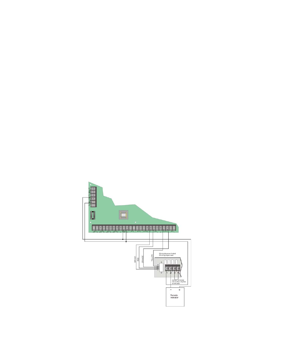
2.
Wire the 5220 to the control panel using the four-wire pigtail provided as shown in Figure 4-35. This dia-
gram also shows how to connect the 5220 to the remote indicator. Do not install an EOL resistor in the ter-
minals of the NAC circuit used for this application.
3.
Connect earth ground wire to the 5220 chassis with mounting screw.
4.
Program the NAC circuit used as continuous and non-silencing. Refer to Section 7.5 for point programming,
Section 7.4 for group settings, and Section 7.3 for zone settings and mapping.
5.
If necessary, adjust loop current using the potentiometer (R10) on the 5220 board. Normal loop current is 2-
to-8 mA with a 1k ohm remote station receiving unit. Maximum loop resistance is 3k ohm.
Figure 4-35 Polarity Reversal Connection Using the 5220 Module
Note:
NAC circuit 1 and Relay 2
used as examples. Either
NAC circuit and Relay
Not suitable for remote station protected premises service
where separate transmission circuits are required for fire
supervisory (if applicable), and trouble signals.
circuit can be used.
Program Relay
for Alarm.
Max Voltage: 27.4 VDC
Max Current: 1 Amp