1 single interlock zone releasing, 1 single interlock zone releasing -13 – SilentKnight 5700 User Manual
Page 145
Model 5700 Installation and Operation Manual
151295
8-13
Table 8-2: Approved Releasing Solenoids
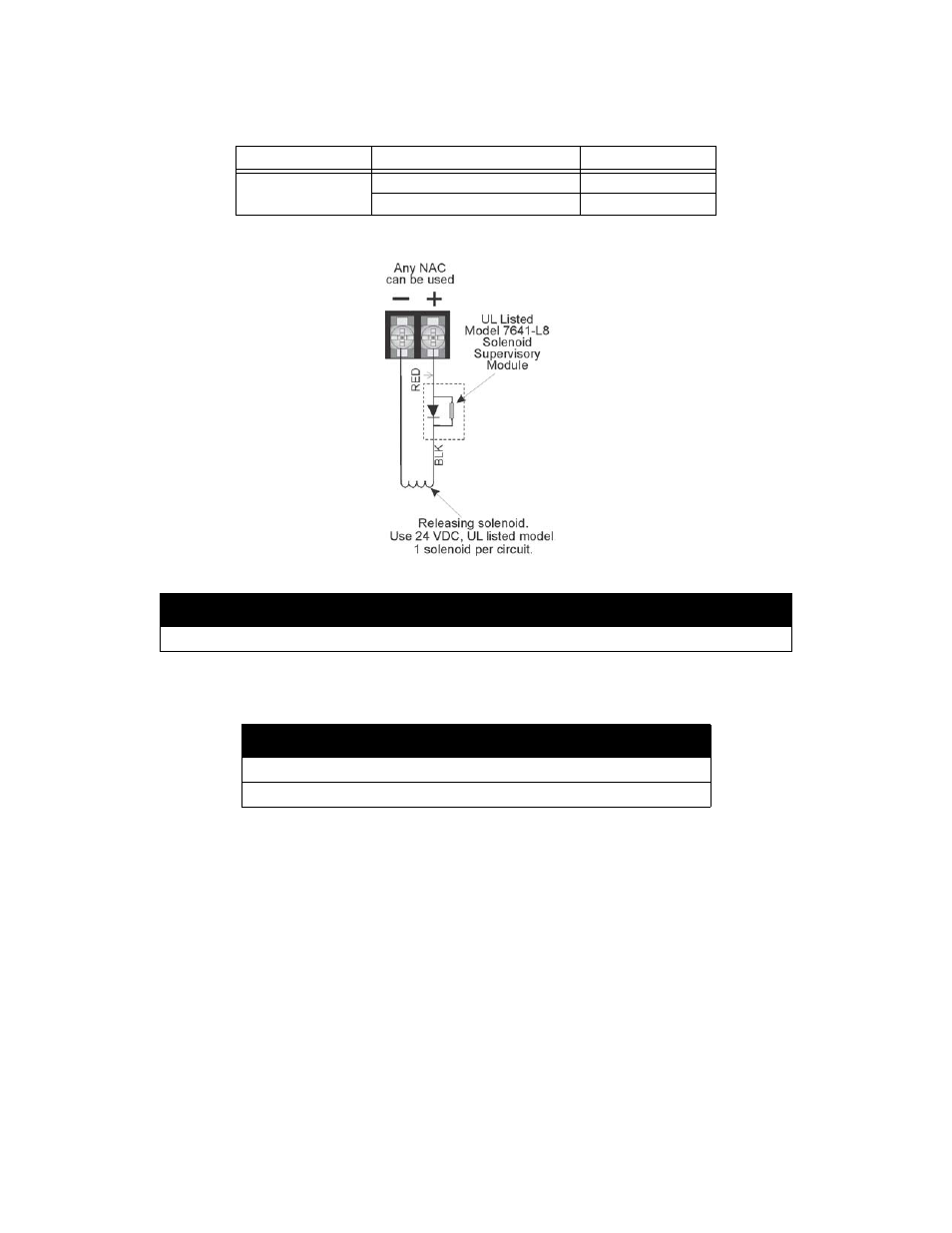
Figure 8-4 Wiring Configuration for Solenoid
8.6.1
Single Interlock Zone Releasing
A single interlock zone utilizes a minimum of two addressable detectors, and a designated manual release switch.
Conditions Required for an Pre-Alert Output Activation
If any single addressable detector is activated, the “Pre-Alert” output will activate and the “Pre-Alarm” output
will deactivate. This alerts the user that the initial stages required for a release condition are present. (Also refer
to Table 8-3.)
Manufacturer
Part Number
Rating
Asco
T8210A107
24 VDC, 2.5A
8210G207
24 VDC, 2.5A
Important!
Detectors must be installed at 0.7 times the linear spacing as described in NFPA 72.
Important!
Only addressable detectors can be used. No conventional detectors can be used.
Each Single Interlock Zone input requires at least one manual release switch.
The Model 7641-L8
Must be located
at the solenoid.
*
*When ordering request PN
7641-L8