Port (db9) 1e/2e installation – Comtrol Hub DeviceMaster User Manual
Page 24
24 - Hardware Installation
DeviceMaster Installation and Configuration Guide: 2000594 Rev. A
Hardware Installation
2-Port (DB9) 1E/2E Installation
Use the following procedure to install DeviceMaster 2-port models with DB9
connectors.
1.
Attach the DeviceMaster 2-Port to the DIN rail adapter.
2.
Connect the power supply and apply power to the DeviceMaster using the
power supply specifications on the product label and the following
information.
Observe proper ESD techniques when connecting and disconnecting the
DeviceMaster.
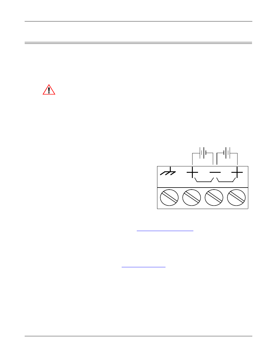
a.
Insert the earth ground wire into the chassis ground screw terminal.
Note: The chassis ground connection is made only if the DIN rail is NOT
connected to earth ground.
b.
Insert the DC positive wire into one of the + screw terminals and the DC
return wire into the - screw terminal.
A second redundant power supply can be connected to the unit by inserting
the DC positive wire into the other + screw terminal and the DC return
wire into the - screw terminal.
The DeviceMaster will
continue to operate if one
of the two connected power
supplies should fail.
If you purchased the
Comtrol power supply
(separately), the wires are
identified below:
• Red = 6-30VDC
positive
• White = 6-30VDC
return
• Black = chassis
ground
If you did not purchase a
power supply from
Comtrol for the
DeviceMaster, see
on Page 139 for power
requirements.
c.
Use a small flat head screw driver to lock the wires into place.
d.
Verify that each wire has been tightened securely.
e.
Connect the power supply to a power source.
Note: Do not connect multiple units until you have changed the default IP
address, see
Caution
PW1
PW2
Return†
Positive†
Positive†
Chassis
Ground†
† Wire gauge: AWG 12-22
6-30VDC