Comtrol Hub DeviceMaster User Manual
Page 21
DeviceMaster Installation and Configuration Guide: 2000594 Rev. A
Hardware Installation - 21
Hardware Installation
3.
Use a small flat head screw to lock the wires into place.
4.
Verify that each wire has been tightened securely.
5.
Plug the screw terminal power connector into the DeviceMaster.
6.
Connect the power supply to a power source.
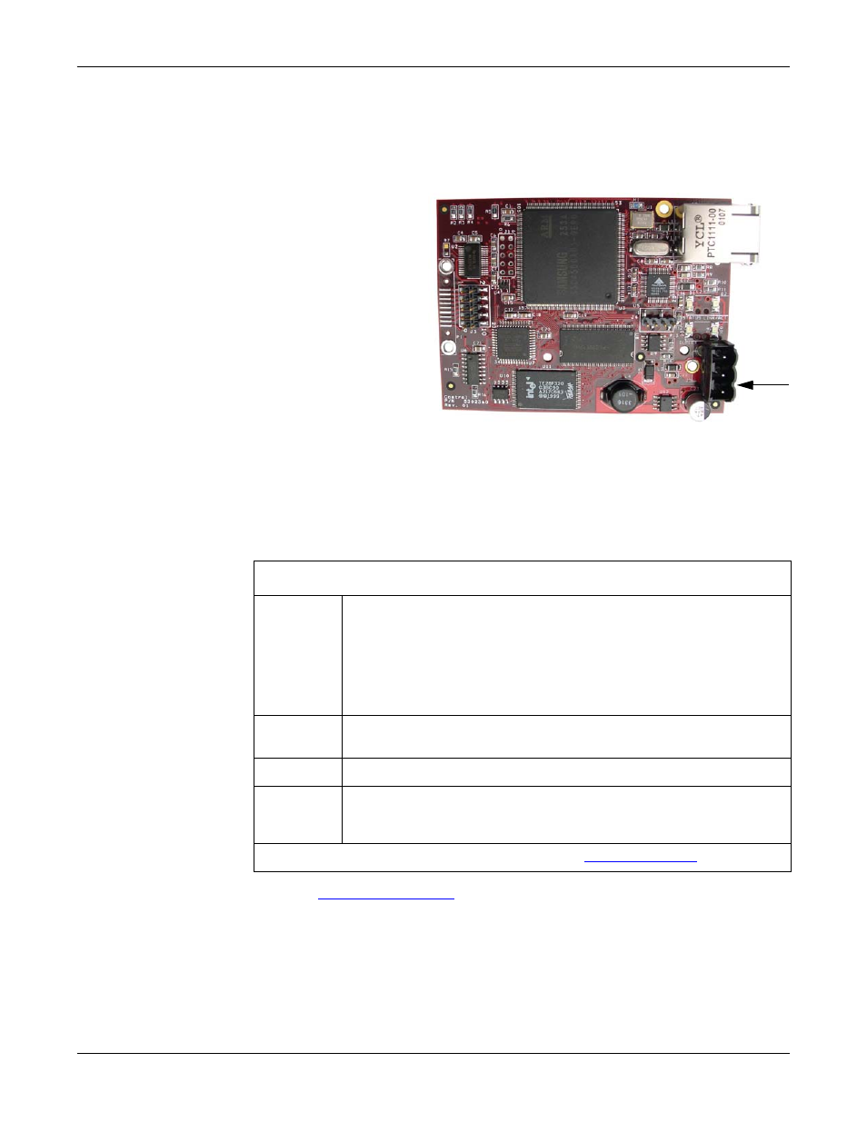
7.
Plug the screw
terminal power
connector into JP1
on the DeviceMaster
by aligning the
scalloped sides.
Note: Align the plug
properly. The
scalloped side
of the screw
terminal
power
connector
should be
aligned with
the scalloped
side of the
power jack on the unit.
8.
Apply power to the DeviceMaster.
9.
Verify the Status LED has completed the boot cycle and network connection for
the DeviceMaster is functioning properly using the table below.
The LEDs are located between the RJ45 connector and the power terminal
block.
10. Go to
on Page 35 for default network settings and how to
configure the DeviceMaster for use.
1-Port Embedded LED Descriptions
Status
When lit, the amber Status LED (D1) on the DeviceMaster
indicates the devices is fully powered and has completed the boot
cycle.
Note: The Status LED flashes for approximately 15 seconds while
booting. When the Bootloader completes the cycle, the LED
has a solid, steady light that blinks approximately every 10
seconds.
Link/Act
When lit, the red Link/Act LED (D2) indicates a working Ethernet
connection.
Duplex
When lit, the red Duplex (D3) LED indicates full-duplex activity.
100
When lit, the red 100 (D4) LED indicates a working 100 MB
Ethernet connection (100 MB network, only). If the LED is not lit,
it indicates a 10 MB Ethernet connection.
Note: For additional LED information, go to the
LEDs
JP1