Application system configuration, Application system configuration -3, Connector cable part numbers – KEYENCE CV-H5N User Manual
Page 13
1
1-3
CV-H5N-M-WW-NO1-E
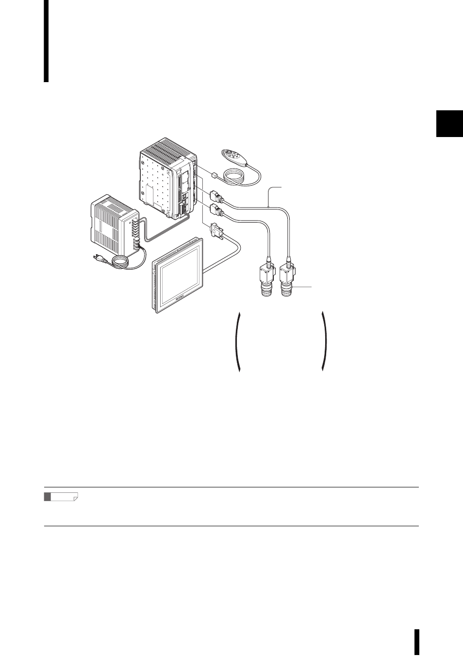
Application System Configuration
This example portrays a system with two cameras connected.
■ Connector cable part numbers
•
Ethernet
: OP-66843
•
USB
: OP-66844
•
RS-232C
: OP-26486 (D-dub 9-pin female connector)
OP-26485 (D-dub 25-pin male connector)
OP-26487 (Straight cable)
Reference
Up to 8 devices can be connected on the network. However, only one CV-5001 Series controller can be connected via USB or
RS-232.
Console
(OP-42342)
Controller unit
CV-5701/5501/5001
24VDC power supply
CA-U2 (Optional)
Camera cable
CV-C3 (3m) (Optional)
Monitor
CA-MP80
(Optional)
Lens (Optional)
Camera 1
SD card (256 MB)
(To be inserted in the SD card slot of the controller unit)
*1GB for the CV-5701
CV-200C
*1
/CV-035C
CV-200M
*1
/CV-035M
CV-S200C
*1
/CV-S035C
CV-S200M
*1
/CV-S035M
CV-H100C
*1
/CV-H035C
CV-H100M
*1
/CV-H 035M
CV-H200C
*1
/CV-H200M
*1
CV-H500C
*2
/CV-H500M
*2
Camera 2
(Sold separately)
*1 Can be connected to the CV-5701 and CV-5501.
*2 Can be connected to the CV-5701 only.