Leds and led screens – Bio-Rad ChromLab™ Software User Manual
Page 81
LEDs and LED Screens
Instrument Guide
| 79
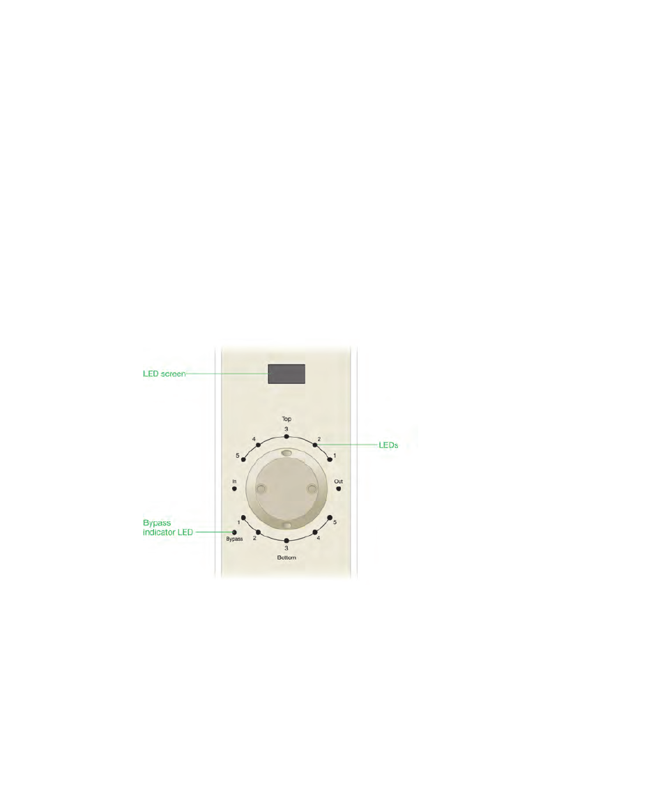
LEDs and LED Screens
The modules on the NGC system are fitted with light emitting diodes (LEDs) that are
located next to ports on the valves and on the inlet and outlet tubing connections
for pumps and all detectors (including the UV detectors and the air sensors).
Depending on the module, LEDs indicate
Flow from the system pumps (green LEDs)
Flow from the sample pump (blue LEDs)
Point-to-Plumb flow path (pulsing green LEDs)
Several modules on the NGC system also have LED screens that display their
current status.
When the NGC system has been inactive for two hours the LED display screens on
the instrument turn off, the touch screen dims, and a dialog box appears on the
touch screen informing you that the system is in standby mode. You can take the
system out of standby mode by touching OK in the dialog box, starting the system
pumps by initiating a manual or method run, or clicking on a module in the fluidic
scheme that has an LED display.