Interpreting the cable loss measurement – Bird Technologies SA-6000EX User Manual
Page 61
Measure Match Mode
45
9. Connect the phase stable cable to one end of the cable under test.
10. Connect the Short connection on the Cal Combo unit to the other
end of the cable being tested.
11. Wait at least 10 seconds to allow the trace to update.
12. Hold the trace on the screen (See Measurement Hold, page 33).
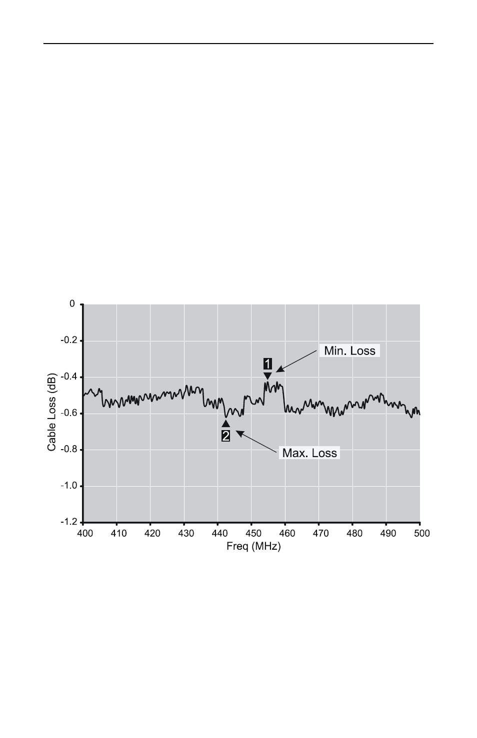
13. Place a triangle-style marker (mark 1) at the minimum loss point
within the frequency band on the trace (refer to Markers, page 34).
14. Place a triangle-style marker (mark 2) at the maximum loss point
within the frequency band on the trace.
15. If appropriate, save and label the trace (refer to Save Trace, page 80).
Interpreting the Cable Loss Measurement
The graph below shows a typical cable loss measurement. Note that the
scale is greatly reduced to show the cable’s variation across frequency.
1. Take the average of M1 and M2. This is the average cable loss
across the frequency band.
2. Compare the loss with the manufacturer’s specified loss for a cable
of this length. If they do not correspond, retake the measurement,
then check the cable for problems.
3. The Cable Loss for a good cable should be flat across the frequency
band.