Chapter 6 - frame 10 mechanical installation, Minimum mounting clearances, Chapter 6 – Rockwell Automation 20D PowerFlex 700H and 700S Frame 9...14 Drives User Manual
Page 71: Frame 10 mechanical installation, Chapter
Rockwell Automation Publication PFLEX-IN006E-EN-P - July 2013
71
Chapter
6
Frame 10 Mechanical Installation
Most start-up difficulties are the result of incorrect wiring. Every precaution must
be taken to assure that the wiring is done as instructed. All information in
Chapter 1 “General Installation Information” and in this chapter must be read
and understood before the actual installation begins.
Minimum Mounting
Clearances
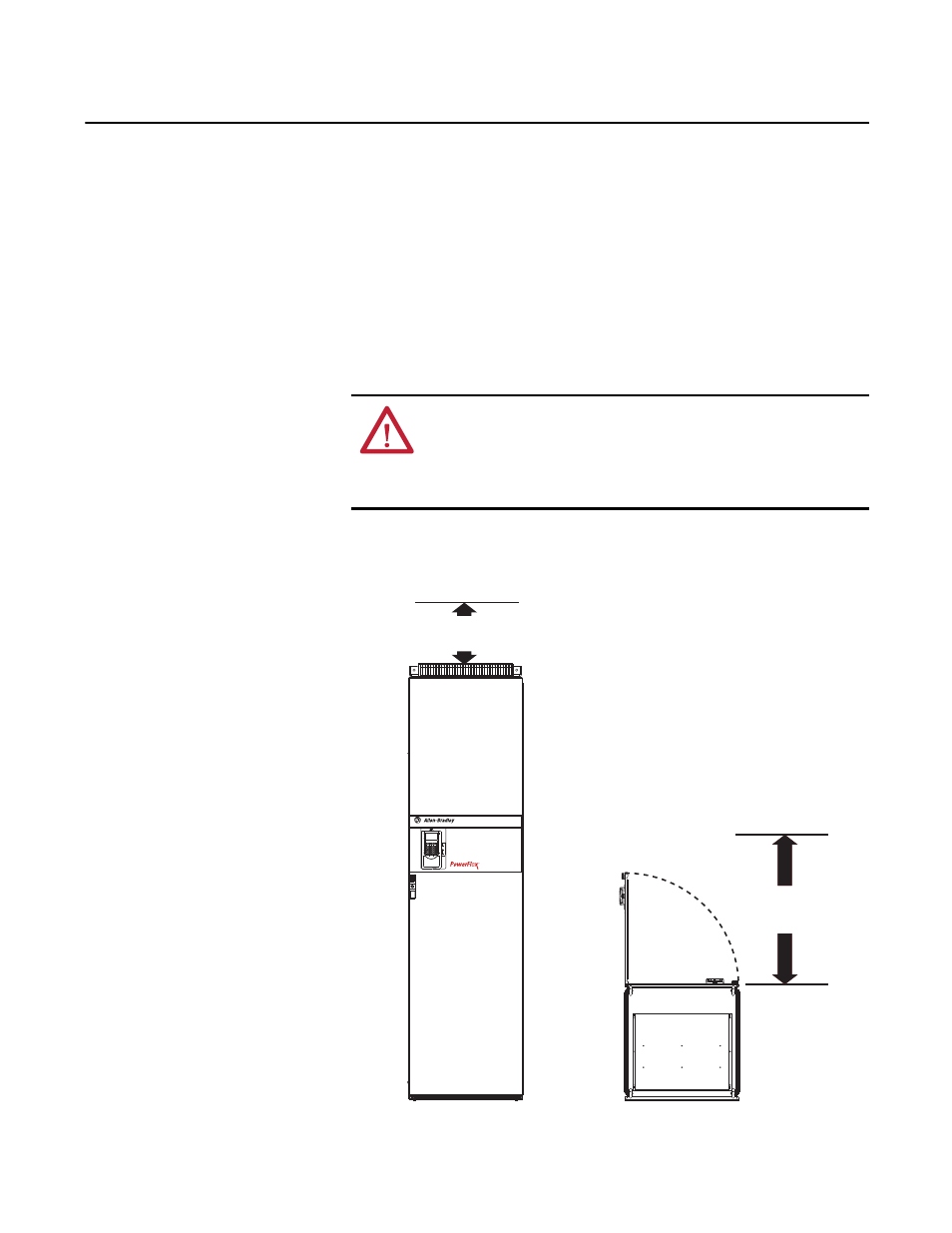
Figure 20 - Enclosure Codes: A (NEMA/UL Type 1, IP21), M (NEMA/UL Type 1, IP21 w/Conformal
Coat), H (NEMA/UL Type 12, IP54) and W (NEMA/UL Type 12, IP54 w/Conformal Coat)
ATTENTION: The following information is merely a guide for proper installation.
Rockwell Automation, Inc. cannot assume responsibility for the compliance or
the noncompliance to any code, national, local or otherwise for the proper
installation of this drive or associated equipment. A hazard of personal injury
and/or equipment damage exists if codes are ignored during installation.
200 mm
(7.87 in.) Min.
800 mm
(31.50 in.) Min.
800 mm
(31.50 in.) Min.
Enclosure Code A (NEMA/UL Type 1, IP21) Shown