8 replacement of components – Rockwell Automation FlexPak 3000 Power Module SW-Version 4.3 User Manual
Page 81
REPLACEMENT PARTS and ACCESSORIES
49’1340 e
FlexPak 3000
8-1
8.0
Replacement of components
Use original spare parts only.
Selection according to Tables 8-1 to 8-6.
The location of the parts is shown on the layout
label inside the U-frame.
5
6
7
8
4a
4
3
2
1
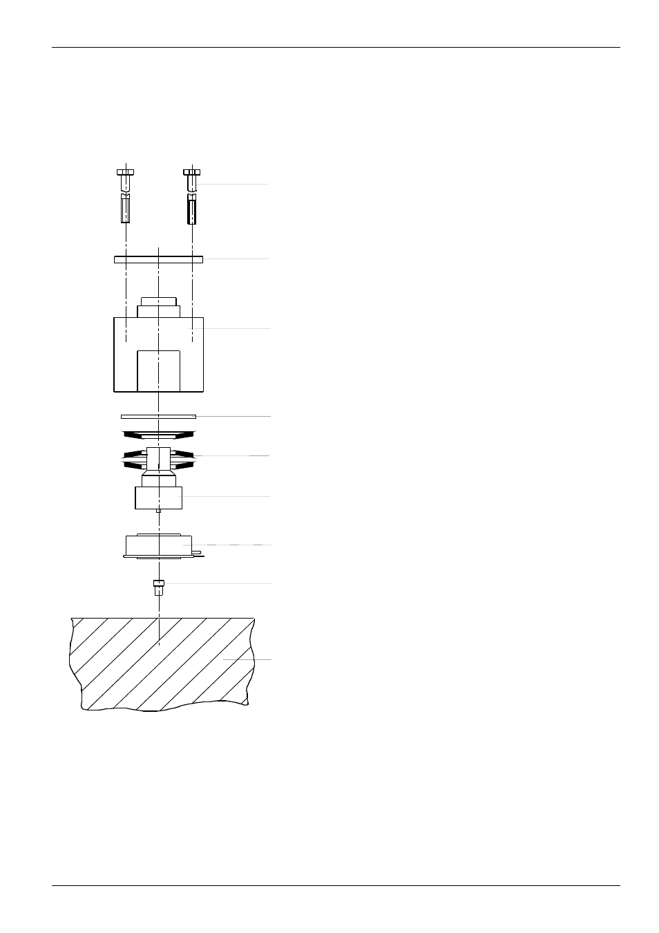
(1) Screws
(2) Steel plate
(3) Housing
(4a) Flat washer
(4) Plate springs
(5) Stamp
(6) Semiconductor
(7) Centering bolt
(8) Heatsink
Replacement of a thyristor or thyristor
module Type 25 - 800 A
•
Loosen and swing out regulator and Interface
assembly
•
Remove bus bars above the thyristors
•
Remove gate leads of the thyristor concerned
•
Unscrew thyristor or thyristor module
•
Before mounting the new thyristor or thyristor
module, coat the side, which is in contact with
the heat sink, with a thin layer of heat
conducting paste.
For units 800 A:
NOTE: for safe and easy mounting of thyristors
on 800 A units we recommend the tool
PN 050.00.00
•
Insert thyristor into box-clamp and put the
package on the centering bolt on the heatsink
•
Fasten the four hexagon bolts by hand until
all slack is taken out and take care that the
clamp housing stays parallel to the heatsink.
•
Tighten each bolt by half a revolution at one
time with hexagonal torque socket spanner 8
mm (10 mm), diagonally.
NOTE: Observe recommended torque!
•
Repeat the procedure until the clamp is held
down firmly to the heatsink on each side.
•
Re-connect gate leads
•
Screw on bus bars.
NOTE: Before replacing a thyristor or thyristor
module the gate and cathode faston
connectors must be checked for
conductivity.