Rockwell Automation FlexPak 3000 Power Module SW-Version 4.3 User Manual
Page 137
APPENDIX B
49’1340 e
FlexPak 3000
B-33
WARNING
:
When analog inputs or network registers are used to control current limits, bipolar values are permitted
for the positive and negative current limits of the current and speed loops. Extreme care must be
exercised when setting the current limit values in this case. If the negative current limit is set to a non-
zero value, the current loop reference will be clamped to this minimum value, possibly causing
unexpected motor or machine operation, including rapid acceleration or overspeed.
Failure to observe this precaution could result in bodily injury.
If you change
NEG CUR LIM INV EN
(P.226),
POS CURRENT LIM SEL
(P.223) and
NEG CURRENT LIM SEL
(P.224) are automatically set to
REGISTER
. When this occurs, an alarm (A00052) is generated to notify
you of a possible change in the current limits. Make sure the settings of
POS CURRENT LIM SEL
(P.223),
NEG CURRENT LIM SEL
(P.224),
POSITIVE CURRENT LIM
(P.005), and
NEGATIVE CURRENT LIM
(P.006) are
correct for your application before operating the drive.
Typically the state of the inverter should only change state during drive setup. Therefore, this should be
an infrequent event.
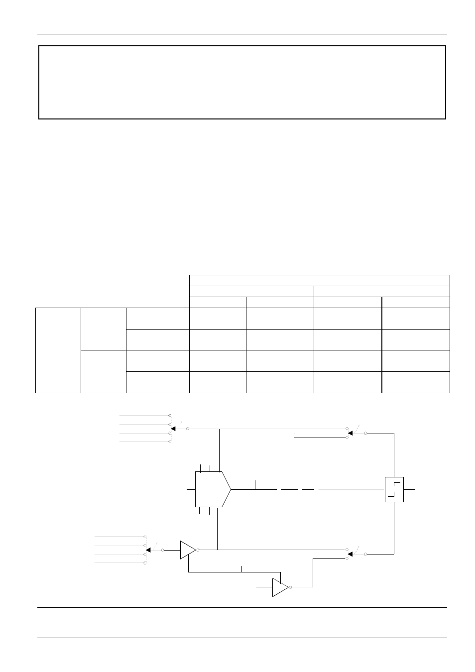
The positive limit register will always remain in the range 0 to MAXIMUM CURRENT.
The absolute value of the negative limit register would be constrained to the range 0 to MAXIMUM
CURRENT. The sign of the negative current limit value will be automatically adjusted according to the
state of the negative current limit inverter. For example, if the inverter is enabled and the negative
current limit is 10.0 A, then the negative current limit will be changed to -10.0 A when the inverter is
disabled. The negative limit register value will be clamped to zero for non-regenerative drives.
DRIVE TYPE
REGEN
NON-REGEN
low limit
high limit
.
low limit
high limit
Positive
0 Maximum 0 Maximum
ENABLE
Current Lim
Current Current
Inverter
Negative
0 Maximum 0
0
State
Current Lim
Current
Positive
0 Maximum 0 Maximum
DISABLE
Current Lim
Current Current
Negative
-Maximum 0
0
0
Current Lim
Current'
(SPD LOOP OUTPUT)
PI
KP HI
WLD LO
POSITIVE CURRENT LIM
POS CURRENT
LIM SEL
*REGISTER
ANALOG IN 1
ANALOG IN 2
NETW IN REG 1, 2, 3
From Network
From I/O Expansion
Inputs Block Diagram
{
P.005
P.299
P.223
NEGATIVE
CURRENT LIM
ANALOG IN 2
NETW IN REG 1, 2, 3
From Network
From I/O Expansion
Inputs Block Diagram
{
NEG CURRENT
LIM SEL
*REGISTER
ANALOG IN 1
EN
P.006
P.224
(A)
(B)
(B)
(A)
INIT
RST
SPEED LOOP
CURRENT LOOP
HI
LO
LIMIT
P.005
EN
NEG CURRENT LIM INV EN 3)
P.226
POS CURRENT LIM
* SPD LOOP CUR LIM
REGISTER
CML REF LIMIT
SELECT
P.311
* SPD LOOP CUR LIM
REGISTER
CML REF LIMIT SELECT
P.311
NEG CURRENT LIM
P.006