Motion axis state diagram, Stopping errorstop standstill disabled homing, Continuous motion discrete motion – Rockwell Automation 2080-LC50 Micro830 and Micro850 Programmable Controllers User Manual User Manual
Page 92
78
Rockwell Automation Publication 2080-UM002F-EN-E - December 2013
Chapter 7 Motion Control with PTO and PWM
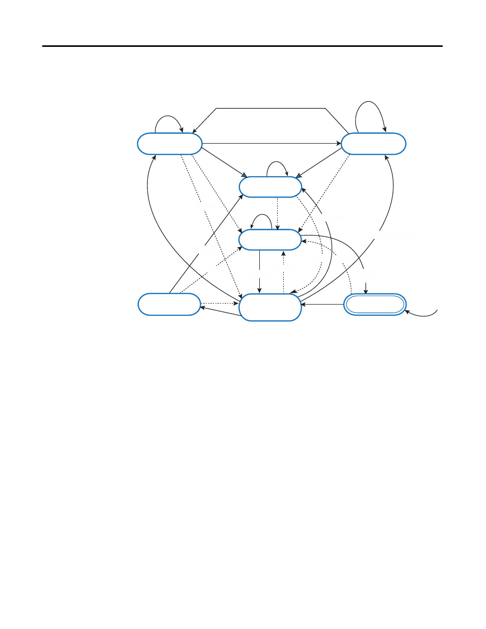
Motion Axis State Diagram
Continuous
Motion
Discrete
Motion
Stopping
ErrorStop
StandStill
Disabled
Homing
MC_MoveAbsolute
MC_MoveRelative
MC_Halt
MC_MoveAbsolute; MC_MoveRelative; MC_Halt
MC_MoveVelocity
MC_MoveVelocity
MC_Stop
MC_Stop
MC_Stop
Done
Error
Error
MC_Stop
MC_Reset and
MC_Power.Status=FALSE
MC_Home
Done
Error
MC_MoveAbsolute
MC_MoveRelative
Error
MC_Reset
MC_MoveVelocity
Note 5
Note 3
Note 2
Note 4
Error
Note 6
Note 1
NOTES:
(1) In the ErrorStop and Stopping states, all function blocks (except MC_Reset), can be called although they will not be executed.
MC_Reset generates a transition to the Standstill state. If an error occurs while the state machine is in the Stopping state, a transition to
the ErrorStop state is generated.
(2) Power.Enable = TRUE and there is an error in the Axis.
(3) Power.Enable = TRUE and there is no error in the Axis.
(4) MC_Stop.Done AND NOT MC_Stop.Execute.
(5) When MC_Power is called with Enable = False, the axis goes to the Disabled state for every state including ErrorStop.
(6) If an error occurs while the state machine is in Stopping state, a transition to the ErrorStop state is generated.