Hsc inputs and wiring mapping – Rockwell Automation 2080-LC50 Micro830 and Micro850 Programmable Controllers User Manual User Manual
Page 129
Rockwell Automation Publication 2080-UM002F-EN-E - December 2013
113
Use the High-Speed Counter and Programmable Limit Switch Chapter 8
When using HSC function blocks, it is recommended that you:
• set HSCAppData underflow setting (UFSetting) and low preset setting
(LPSetting) to a value less than 0 to avoid possible HSC malfunction
when the HSC accumulator is reset to 0.
• set HSCAppData overflow setting (OFSetting) and high preset setting
(HPSetting) to a value greater than 0 to avoid possible HSC malfunction
when the HSC accumulator is reset to 0.
In some cases, a sub counter will be disabled by master counter mode. See the
section HSC Mode (HSCAPP.HSCMode) on page 118.
HSC Inputs and
Wiring Mapping
All Micro830 and Micro850 controllers, except 2080-LCxx-xxAWB, have
100 kHz high-speed counters. Each main high-speed counter has four dedicated
inputs and each sub high-speed counter has two dedicated inputs.
TIP
You must set a proper value for the variables OFSetting, HPSetting, and
UFSetting before triggering Start/Run HSC. Otherwise, the controller will
be faulted. (Setting a value for LPSetting is optional for certain counting
modes.)
To learn more about HscAppData variable input, see
.
TIP
HSC0 is used in this document to define how any HSC works.
IMPORTANT
The HSC function can only be used with the controller’s embedded I/O.
It cannot be used with expansion I/O modules.
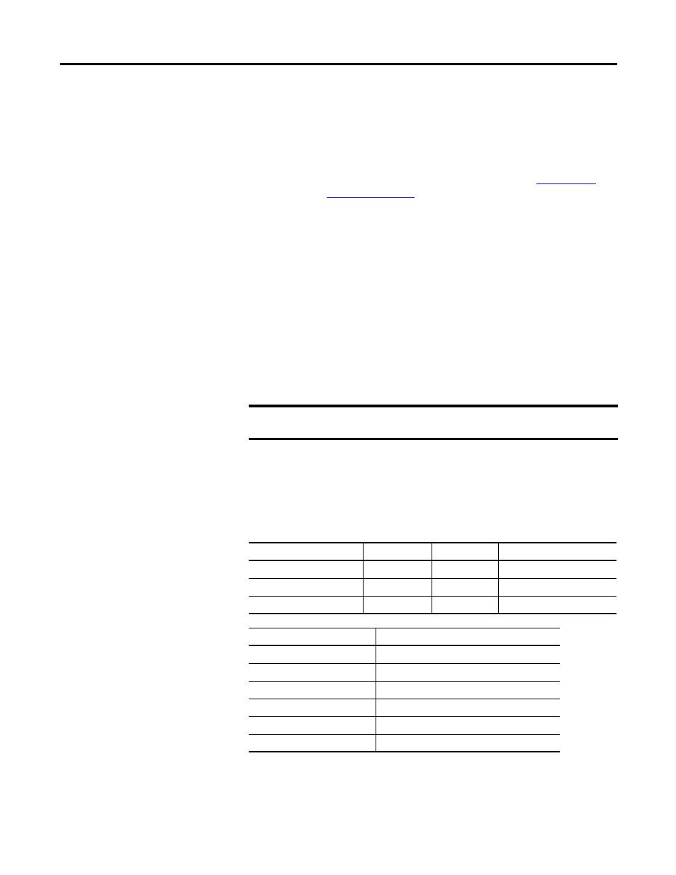
Micro830 and Micro850
High Speed Counters
10/16-point
24-point
48-point
Number of HSC
2
4
6
Main high-speed counters
1 (counter 0)
2 (counter 0,2)
3 (counters 0, 2 and 4)
Sub high-speed counters
1 (counter 1)
2 (counter 1,3)
3 (counters 1, 3 and 5)
High Speed Counter
Inputs used
HSC0
0, 1, 2, 3
HSC1
2, 3
HSC2
4, 5, 6, 7
HSC3
6, 7
HSC4
8, 9, 10, 11
HSC5
10, 11