Pls example, Setting up the pls data – Rockwell Automation 2080-LC50 Micro830 and Micro850 Programmable Controllers User Manual User Manual
Page 155
Rockwell Automation Publication 2080-UM002F-EN-E - December 2013
139
Use the High-Speed Counter and Programmable Limit Switch Chapter 8
At that point, the next presets (HSCHP and HSCLP) defined in the PLS data
become active.
When the HSC counts to that new preset, the new output data is written
through the HSC mask. This process continues until the last element within the
PLS data block is loaded. At that point the active element within the PLS data
block is reset to zero. This behavior is referred to as circular operation.
If invalid data is loaded during operation, an HSC error is generated and causes a
controller fault.
You can use the PLS in Up (high), Down (low), or both directions. If your
application only counts in one direction, ignore the other parameters.
The PLS function can operate with all of the other HSC capabilities. The ability
to select which HSC events generate a user interrupt are not limited.
PLS Example
Setting Up the PLS data
Using Connected Components Workbench, define the PLS data HSC_PLS’s
dimension as [1..4].
TIP
The HSCHPOutput is only written when HSCHP is reached. The
HSCLPOutput is written when HSCLP is reached.
TIP
Output High Data is only operational when the counter is counting up.
Output Low Data is only operational when the counter is counting
down.
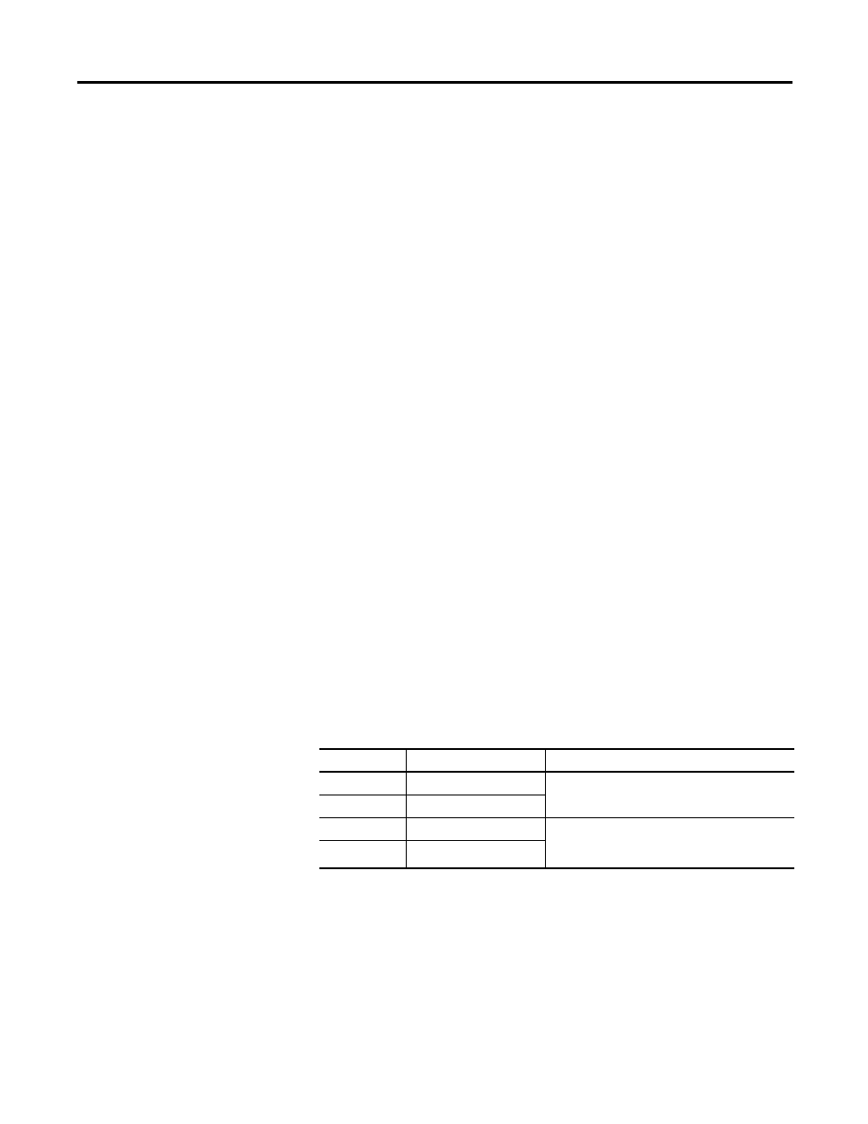
PLS Data Definition
Data
Description
Data Format
HSCHP
High Preset
32-bit signed integer
HSCLP
Low Preset
HSCHPOutput
Output High Data
32-bit binary
(bit 31--> 0000 0000 0000 0000 0000 0000 0000
0000 <--bit 0)
HSCLPOutput
Output Low Data