Rockwell Automation 1408-EMxx PowerMonitor 1000 Unit User Manual
Page 61
Rockwell Automation Publication 1408-UM001D-EN-P - September 2013
61
Explicit Messaging Chapter 5
Message setup is complete for Serial communication.
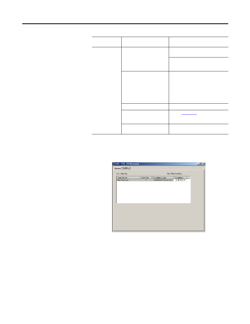
4. Click the MultiHop tab if configuring Ethernet communication.
5. Enter the IP Address of the power monitor in the To Address box.
Message setup is complete.
RSLogix5 Software - Message Setup Using PLC5 or SLC Typed
Read/Write
The following is an example of how to set up your message instruction to read or
write single or multiple elements to a power monitor using PLC5 or SLC Typed
messages in RSLogix5. This setup applies to PLC5 programmable logic
controllers.
Serial
Data Table Address (This
Controller)
Read: This is the controller tag in which to
store the data being read
Write: This is the controller tag that stores
the value to be written to the power
monitor.
Size in Elements
This is the number of elements being read
or written to. If you are performing a
single element read or write, then this
value should be 1. If you are performing a
multiple element read or write, then this
should be the number of elements after
the source element that you wish to read
or write.
Channel
0
Data Table Address (Target
Device)
for the address of the
specific data value you’re reading or
writing to.
Local Node
This is the serial node address of your
power monitor.
Communication
Type
Parameter
Choice