Lcd screen display and configuration menu map, Figure 2 - menu navigation, Figure 3 - main menu, page 1 chart key – Rockwell Automation 1408-EMxx PowerMonitor 1000 Unit User Manual
Page 17
Rockwell Automation Publication 1408-UM001D-EN-P - September 2013
17
PowerMonitor 1000 Overview Chapter 1
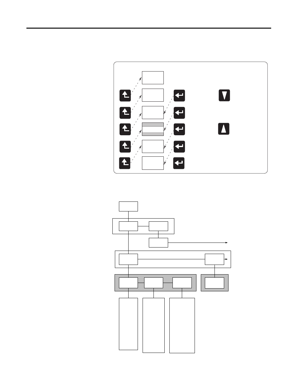
This diagram shows how to navigate in the display and configuration menu.
Figure 2 - Menu Navigation
LCD Screen Display and Configuration Menu Map
Figure 3 - Main Menu, Page 1
Chart Key
Default
Screen
Select
Level 1
Level 2
Level 4
Level 3
Next Item
(within current level)
Previous Item
(within current level)
Default
Screen?
Display
Config
Setup
Program
Password?
Display
Metering
I1
I2
I3
I Average
V LN1
V LN2
V LN3
V L12
V L23
V L31
V LN Avg
V LL Avg
Frequency
Unbalance V
Unbalance I
Display
Metering Volts
Amps
Frequency(1)
Metering
Power(1)(2)
Level 1
Level 2
Level 3
PF 1
PF 2
PF 3
PF Total
KW 1
KW 2
KW 3
KW Total
KVAR 1
KVAR 2
KVAR 3
KVAR Total
KVA 1
KVA 2
KVA 3
KVA Total
Metering
Energy(1)
Status 1 Cnt
Status 2 Cnt
kWH Fwd
kWH Rev
kWH
kVARH Fwd
kVARH Rev
kVARH
kVAH
kW Demand
kVAR Demand
kVA Demand
PF Demand
kW Proj Demand
kVAR Proj Demand
kVA Proj Demand
Level 4
See Setup
Submenu
(1)
The Catalog Number and Voltage
mode determine which parameters are
displayed.
(2)
Individual phase parameters are not
displayed in Delta modes.