1 configuring i/o modules at the backplane bus, Configuring i/o modules at the backplane bus, 5commissioning the controller – Lenze c300 User Manual
Page 39
5
Commissioning the controller
5.5
I/O system 1000 at the backplane bus of a cabinet controller
39
Lenze · Controller | Parameter setting & programming · Reference Manual · DMS 1.5 EN · 04/2014 · TD17
_ _ _ _ _ _ _ _ _ _ _ _ _ _ _ _ _ _ _ _ _ _ _ _ _ _ _ _ _ _ _ _ _ _ _ _ _ _ _ _ _ _ _ _ _ _ _ _ _ _ _ _ _ _ _ _ _ _ _ _ _ _ _ _
5.5
I/O system 1000 at the backplane bus of a cabinet controller
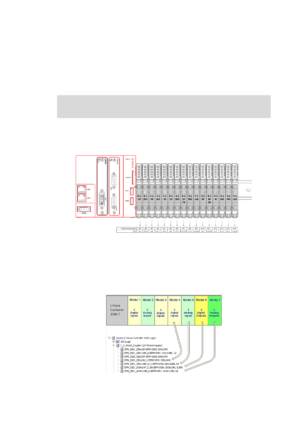
The Cabinet Controllers 3200 C and c300 allow for a direct connection of the I/O system 1000 to the
integrated backplane bus.
The modules of the I/O system 100 connected to the backplane bus of the Controller can be
parameterised in the »PLC Designer«.
5.5.1
Configuring I/O modules at the backplane bus
The following illustration is a schematic representation of the controller hardware structure
including I/O modules.
The I/O system 1000 includes the following components:
• I/O module coupler for voltage supply of the I/O compound modules
• I/O compound modules:
Up to 64 modules are possible which are connected to the Controller 3200 C via the Lenze
backplane bus.
In order to be able to access the modules by means of a PLC program (read input signals/write
output signals), the modules have to be configured in the »PLC Designer«. For this, map the physical
arrangement of the I/O modules in the »PLC Designer«.
[5-4]
Example: mapping the physical arrangement of modules 1...7 in the »PLC Designer«
System manual for I/O system 1000 (EPM-Sxxx)
Here, further information on the parameter setting/configuration can be found.