3 terminology used, Terminology used, 1about this documentation – Lenze c300 User Manual
Page 11
1
About this documentation
1.3
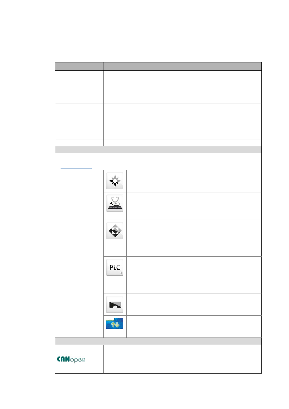
Terminology used
11
Lenze · Controller | Parameter setting & programming · Reference Manual · DMS 1.5 EN · 04/2014 · TD17
_ _ _ _ _ _ _ _ _ _ _ _ _ _ _ _ _ _ _ _ _ _ _ _ _ _ _ _ _ _ _ _ _ _ _ _ _ _ _ _ _ _ _ _ _ _ _ _ _ _ _ _ _ _ _ _ _ _ _ _ _ _ _ _
1.3
Terminology used
Term
Meaning
Controller
The controller is the central component of the automation system which controls the
Logic and Motion functionalities by means of the runtime software.
The controller communicates with the field devices via the fieldbus.
Engineering PC
The Engineering PC and the Engineering tools installed serve to configure and
parameterise the system "Controller-based Automation".
The Engineering PC communicates with the controller via Ethernet.
Fieldbus stations
Devices integrated in the bus system as, for instance, Controller and inverter
Field device
Inverter
Generic term for Lenze frequency inverter, servo inverter
PLC
Programmable Logic Controller
PLC
Programmable Logic Controller (PLC)
UPS
Uninterruptible power system (UPS)
Engineering tools
Software solutions for easy engineering in all phases which serve to commission, configure, parameterise and
diagnose the Lenze automation system.
»EASY Navigator« – provides for orientation
• All convenient Lenze Engineering tools at a glance
• Tools can be selected quickly
• Simplifies the access to the engineering process by its clarity.
»EASY Starter« – easy-to-use tool for service technicians
• For the maintenance of Lenze devices
• For the commissioning of Lenze devices
• Online diagnostics, parameterisation and commissioning
• Loading of ready-to-use applications to the device
»Engineer« – multi-device engineering
• Suitable for all products of the Lenze portfolio
• Easy handling by means of graphical user interfaces
•
Can be used in all engineering phases (project planning, commissioning,
production)
• Parameterisation and configuration of Lenze devices
»PLC Designer« – programming processes
• Creating individual programs
• Programming Logic & Motion according to IEC 61131-3 (AWL, KOP, FUP,
ST, AS and CFC-Editor), based on CoDeSys V3
• Certified function blocks according to PLCopen part 1 + 2
• Graphic DIN 66025 Editor (G code) with DXF import
• Integrated visualisation for the simple representation of processes
»VisiWinNET« – visualisation tool
• Visualise the applications of the automation system
• Create the visualisation/user interface
»Backup & Restore« – back up/restore/update data
• Create data backups
• Restore data after device replacement
• Carry out software update of the Controller
Bus systems
CAN
CAN (Controller Area Network) is an asynchronous, serial fieldbus system.
CANopen® is a communication protocol based on CAN. The Lenze system bus (CAN on
board) operates with a subset of this communication protocol.
CANopen® is a registered community trademark of the CAN user organisation CiA® (CAN
in Automation e. V.).