4 digital signals (overview), 4digital signals (overview), 13 configuration – JUMO 705060 mTRON T - Multifunction Panel 840 Operating Manual User Manual
Page 197
197
13 Configuration
13.18.4 Digital signals (overview)
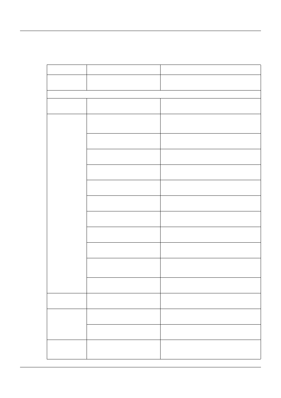
The following table contains all digital signals that are available for connecting to the digital in-
puts of the multifunction panel and for controlling batch reporting.
Category
Signal
Description
Inactive
No signal selected
Central processing unit
Digital variables
Digital variable 1 to 64
Digital variable 1 to 64 (via interface)
Program
generator 1 to
Program
generator 9
Operating contact 1 to 16
Operating contact 1 to 16 of program channels
(in the three program channels, operating con-
tacts with the same name are linked with OR)
Mode: Basic status
Status: Program is not running (basic status)
Mode: Automatic
Status: Program is running (automatic mode,
no delay time or program end time)
Mode: Automatic 1
Status: Program is running (automatic mode,
incl. delay time and program end time)
Mode: Standstill
Status: Program stopped during automatic
mode (time base stopped)
Mode: Delay
Status: Program start delayed (delay time
runs)
Mode: Program end
Status: Program ends (program end time runs,
corresponds to length of end signal)
Mode: Manual
Status: Manual mode
Tolerance band channel 1 to 3
Tolerance band signal of program channel 1 to
3
Batch control
Signal to control the batch recording (OR-
linked signals "Automatic", "Standstill", and
"Program end").
PLC Binary output 28 to 32
Signal of PLC digital output 28 to 32
Limit monitoring
Limit monitoring 1 to 64
Output signal of limit value monitoring 1 to 64
Binary linking
Binary linking 1 to 8
Result of binary linking 1 to 8
PLC Binary output 9 to 32
Signal of PLC digital output 9 to 32
Binary PLC out-
put block 13 to
block 18
PLC Binary output 1 to 32
Signal of PLC digital output 1 to 32