3 wiring and piping for blowback, Figure 5.17 typical diagram for blowback – Yokogawa Multi Channel Oxygen Analyzer System ZR22/AV550G User Manual
Page 97
IM 11M12D01-01E
5-17
5. Wiring
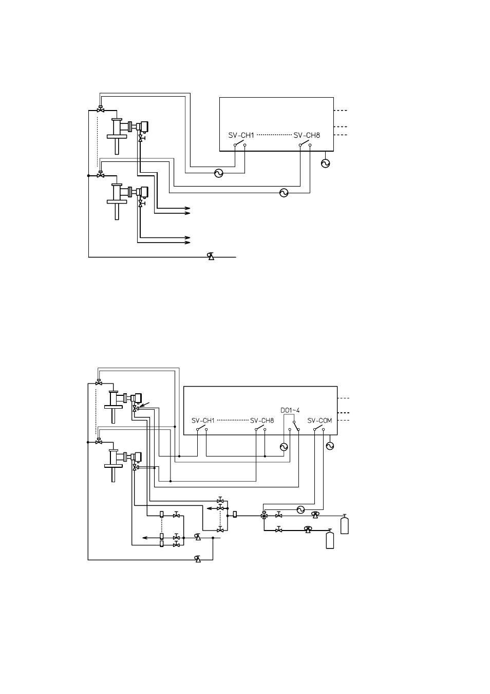
5.3.3
Wiring and Piping for Blowback
Averaging Converter (AV550G)
Analog Output
(Averaged and Individual Output)
Contact Output
Contact Input
Power Supply
Blowback Solenoid Valve
High Temperature
Detector
Stop Valve
Calibration
Gas Line
Reference
Gas Line
Calibration
Gas Line
Reference
Gas Line
To ZA8F Flow Setting Unit
To ZA8F Flow Setting Unit
Instrument Air
Air Set
: If optional 24 V outputs are specified for solenoid valves (Option Code 0/240), no external
power supply for solenoid valves is required. The solenoid valves are powered from the
AV550G Averaging Converter. Never connect external power sources in the wiring for
solenoid valves.
ء
ء
ء
Figure 5.17 Typical Diagram for Blowback
5.3.4
Wiring and Piping for Automatic Calibration and Blowback
Averaging Converter (aV550G)
Analog Output
(Averaged and Individual Output)
Contact Output
Contact Input
Power Supply
Span Gas Cylinder
(Instrument Air)
Zero Gas Cylinder
Pressure Regulator
Solenoid
Valve
Flowmeter
Needle Valve
Calibration Gas Line
Instrument Air
Air Set
Needle Valve
Flowmeter
Reference
Gas Line
Solenoid
Valve
Blowback Solenoid Valve
High Temperature
Detector
Note : If optional 24 V outputs are specified for solenoid valves (Option Code 0/240), this system cannot be established.
This is because the contact to activate a solenoid valve is used in common for autocalibration and blowback.
Figure 5.18 Typical Diagram for Automatic Calibration and Blowback