2 av550g averaging converter, 1 components and function, Components – Yokogawa Multi Channel Oxygen Analyzer System ZR22/AV550G User Manual
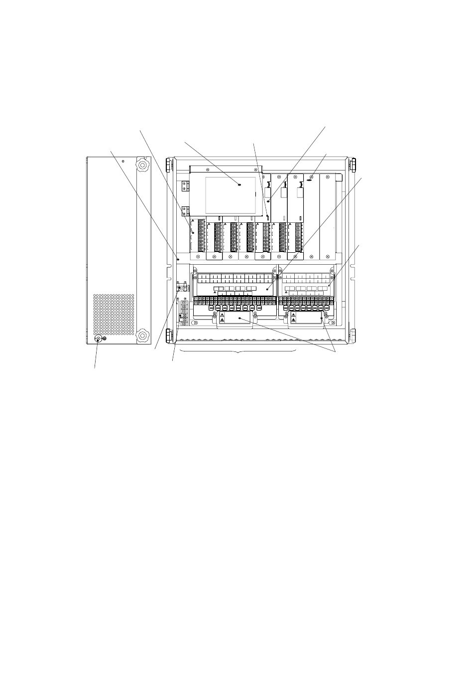
Page 101: Control card, Touch screen display, Status display lamps, Channel cards, Channel slot covers, Basic power supply unit, Expansion power supply unit
IM 11M12D01-01E
6-3
6. Components
6.2
AV550G Averaging Converter
6.2.1
Components and Function
1
2
3
4
5
6
7
8
CELL
TC
CJ
AO
+
+
+
+
-
-
-
-
1
2
3
4
5
6
7
8
CELL
TC
CJ
AO
+
+
+
+
-
-
-
-
1
2
3
4
5
6
7
8
CELL
TC
CJ
AO
+
+
+
+
-
-
-
-
1
2
3
4
5
6
7
8
CELL
TC
CJ
AO
+
+
+
+
-
-
-
-
1
2
3
4
5
6
7
8
CELL
TC
CJ
AO
+
+
+
+
-
-
-
-
1
2
3
4
5
6
7
8
CELL
TC
CJ
AO
+
+
+
+
-
-
-
-
DI2
-
-
-
DI1
+
+
+
Ave-c
Ave-b
Ave-a
8
7
6
5
4
3
2
1
COM
9
Control Card
Controls averaging
calculations, autocalibration
and display functions
Touch Screen Display
Displays data and allows
interactive touch screen
operation.
Status Display Lamps
Green, continuous: Channel card is active
Orange, continuous: Alarm condition
Orange, flashing: Calibration in progress
Red, continuous: Error condition
Channel Cards
Specified number of channel cards is
installed. Send output signals for
individual oxygen concentrations.
Channel Slot Covers
Covers unused channel slots.
Basic Power Supply Unit
Carries heater terminals
and contact terminals for
CH1 to CH4
Expansion Power
Supply Unit
Carries heater terminals
and contact terminals for
CH5 to CH8.
External Protective
Ground Terminal
Power Switch
Main Power Supply
*Cable Shield* Ground Terminals
Protection Covers for Heater
Terminals
ؒ
L
ؒ
N
ؒ
G (connected to internal protective ground
terminal by jumper plate)
ؒ
Internal protective ground terminal
Frame
Figure 6.3 Components and Function of AV550G
6.2.2
Touchpanel Switch Operations
6.2.2.1 Panels and Switches
The averaging converter uses touchpanel switches which can be operated by just
touching the panel display. The display viewed upon power up or during oxygen
concentration measurement varies depending on the number of channel cards installed in
an averaging converter. Data of 4 channels will be displayed if 1 to 4 channel cards are
installed. If more than 4 channel cards are installed, data of 8 channels will be displayed.
Even if the number of channel cards is 4 or less, data of 8 channels will be displayed if
an expansion power supply unit is mounted and a card is installed on any of channels
CH5 to CH8. The display “---” means a channel no card is installed in the channel. As
shown in upper left and right displays in Figure 6.4, data of multiple channels can be
viewed in a single screen, which is called a multi-channel display.