Yokogawa Multi Channel Oxygen Analyzer System ZR22/AV550G User Manual
Page 43
IM 11M12D01-01E
2-24
< Pressure setting for the auxiliary ejector for high-temperature use >
Pressure supply for the auxiliary ejector should be set so that the suction flow of the
measured gas becomes approximately 5 l/min.
To set this, proceed as follows:
(1) In Graph 4, draw a horizontal line from the 5 l/min point. on the vertical axis
(Suction flow: Qg) toward the gas pressure line to be used, to find the point of
intersection.
Draw a line vertically down from the point of intersection to the axis to find the
drive pressure, P (at the ejector entrance).
(2) In Graph 1, determine Po (pressure setting) from L (the distance between the ejector
and the pressure gauge).
(3) Open the needle valve to supply air for the ejector to the pressure gauge until it
indicates the pressure setting, Po.
Note
Qg (the suction flow) may require change according to the conditions of use. Refer to
Section 3.2.2 and Section 4.1.4 for details.
Graph explanation
1) Graph 1 is to compensate for pressure loss in piping between the ejector and the
pressure gauge, and find Po (pressure setting).
2) Graph 2 shows correlation between P (drive pressure) and Qa (air consumption).
3) Graph 3 shows correlation between P (drive pressure) and Pg (suction pressure; when
the measured gas inlet of the ejector is closed).
4) Graph 4 shows correlation between P (drive pressure) and Qg (suction flow) for each
gas pressure.
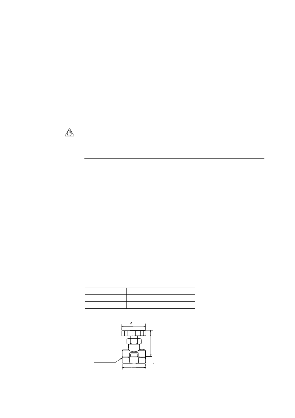
2.6.4
Stop Valve (Part No. L9852CB or G7016XH)
This valve is mounted on the calibration gas line in the system using flow setting unit
for manual calibration.
Standard Specifications
Connection: Rc 1/4 or 1/4 FNPT
Material: SUS 316 (JIS)
Weight: Approx. 80 g
Joint: RC 1/4, Material: SUS 316 (JIS)
Joint: 1/4 NPT, Material: SUS316 (JIS)
T2.9E.EPS
Description
Part No.
L9852CB
G7016XH
F15.EPS
(Full open length)
40
Rc1/4 or 1/4NPT
43
55