Yokogawa Multi Channel Oxygen Analyzer System ZR22/AV550G User Manual
Page 170
IM 11M12D01-01E
10-8
10.2.3 Trend Graph Display Settings
Selecting channels to be displayed
1) On the basic panel display, touch the Graph Display key to display the Trend Graph
display.
2) If you touch anywhere in the Graph display area, the Graph Channel Select display
will appear. The colors of the channel numbers correspond to the colors of the trend
graphs. Grayed-out channels are not selected for display.
3) To suppress display of the Ave-a graph, move the pointer to [Ave-a] and touch the
Enter key. The color of [Ave-a] turns gray, and its trend graph is no longer dis-
played.
Entering the sampling interval
4) On the basic panel display, touch the Setup key to display the Execution/Setup
display.
5) Select [Maintenance] then [Display Setup] and touch the Enter key.
6) Select [Trend Graph] and tough the Enter key.
7) Select [Sample Interval] and touch the Enter key and the numerical entry display
appears. You can enter a value for the sampling interval in the range 1 to 30 seconds.
Setting trend graph vertical scale
8) From the Trend Graph display, select [Upper Limit] and touch the Enter key. The
numerical entry display appears, and you can enter the upper limit value. The lower
limit value can be entered in a similar manner. Both upper and lower limit values can
be entered in the range 0 to 100% O
2
, however the upper limit value must be set
higher than the lower limit value by at least 1% O
2
.
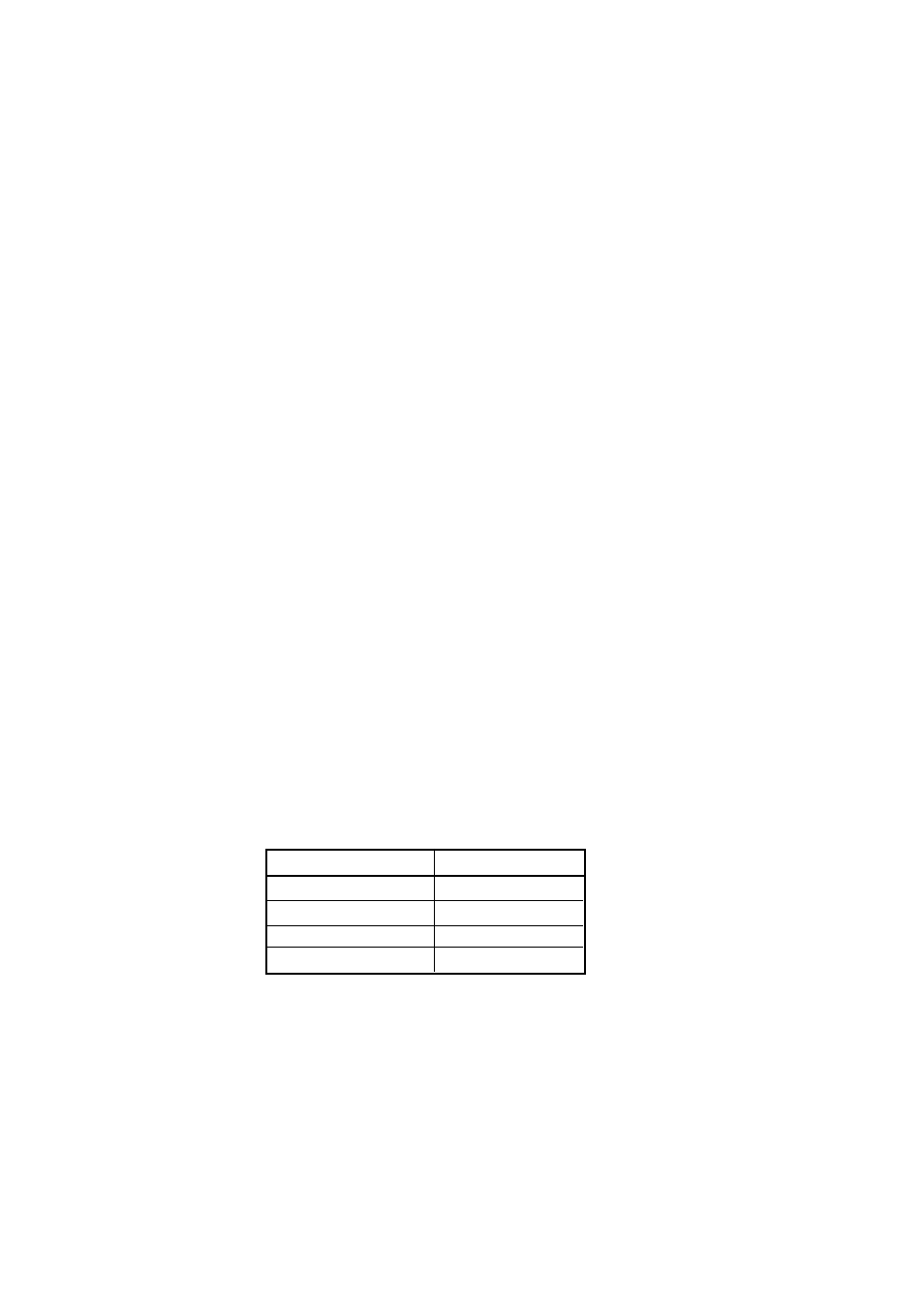
The graph parameters are set to the following default prior factory shipment or
after data initialization.
Table 10.2
Item Initial
value
Displayed channels
All channels
Sampling interval
30 seconds
Upper limit
25% O
2
Lower limit
0% O
2
T10.2E.eps