3 piping for the reference gas, 4 piping to the high temperature probe adapter, 2 wiring holes – Yokogawa Multi Channel Oxygen Analyzer System ZR22/AV550G User Manual
Page 84
IM 11M12D01-01E
5-4
5.1.2
Wiring Holes
The averaging converter has 30 wiring holes. Use holes near the rear for power wiring
(e.g., power cables, detector heater wires, and wiring for solenoid valve contacts and
other contact outputs). For signal wiring (e.g., detector signal lines and analog output
signal lines), use holes near the front.
If more than 30 cables are used and thus more than one cable has to be passed through
one wiring hole, do not allow signal lines and power lines to pass the same hole. Also,
in the averaging converter, the signal lines and power lines should be routed so they can
avoid contact and interference.
A grommet is attached, as standard, to the wiring hole of the averaging converter. An
optional cable gland is available. When a cable gland is not used, make a cable hole in a
grommet.
Wiring Connections:
30 holes
Applicable Cable Hole:
л17 mm maximum for grommet
л6 to л12 mm for cable gland (optional)
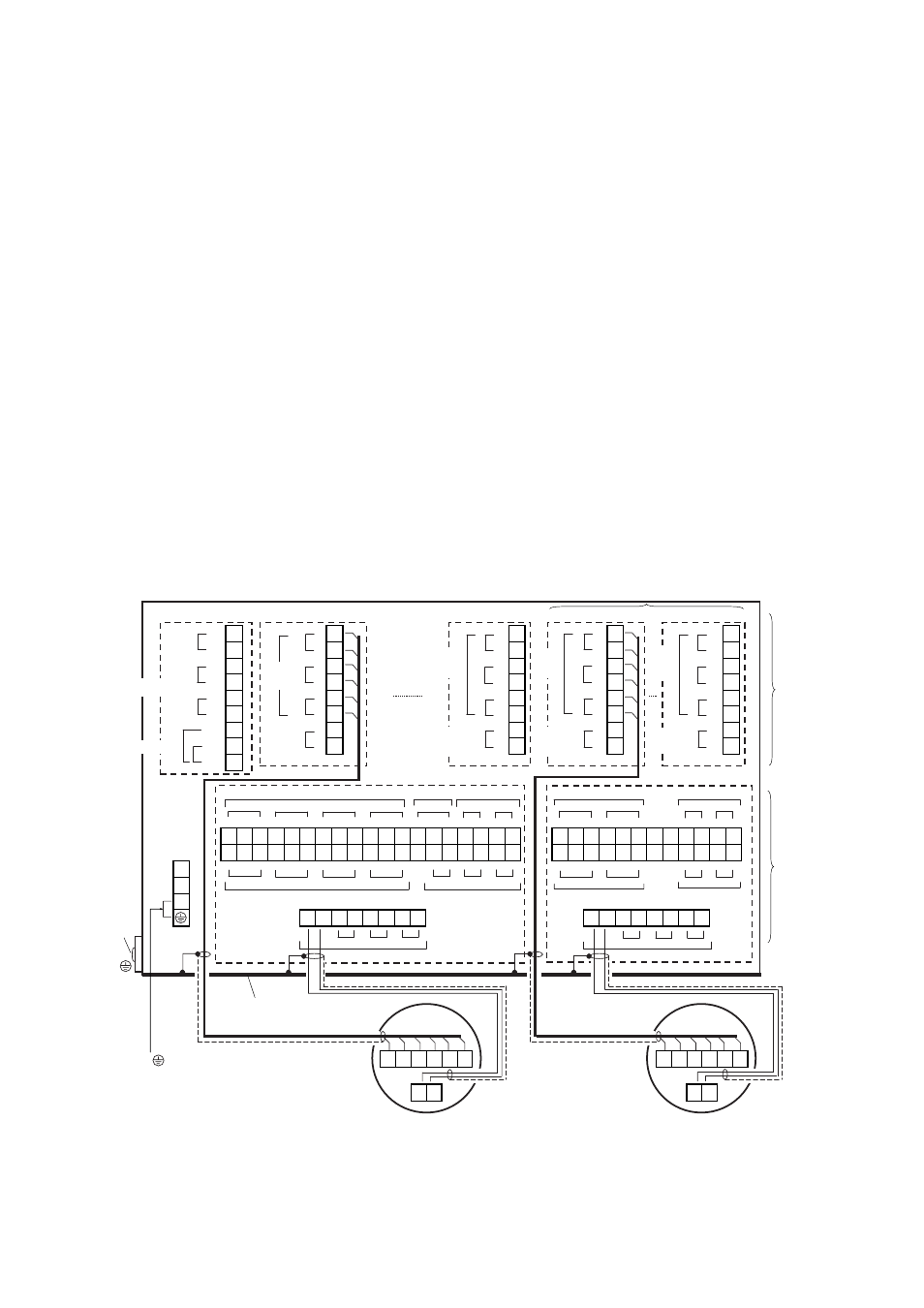
5.1.3
External Wiring Connection Terminals of the Averaging Converter
The connection diagram of the averaging converter is shown in Figure 5.3. The terminal
numbers are indicated on the converter. Care should be taken to make the wiring
connections correctly.
+ 1
+ 1
+
1
+
1
+ 1
- 2
- 2
-
2
-
2
- 2
+ 3
+ 3
+
3
+
3
+ 3
- 4
- 4
-
4
-
4
- 4
+ 5
+ 5
+
5
+
5
+ 5
- 6
- 6
-
6
-
6
- 6
DI1 7
+ 7
+
7
+
7
+
7
DI2 8
- 8
-
8
-
8
- 8
COM 9
C
NC NO
C
NC NO
C NC NO
C NC NO C
NC NO
C
NC NO
C
NC NO
11
12
13
14
15
16
17
19
20 21
22
24
25
26
27
28 29
61 62
63
64
65
66
68
70 71 72
31 32
33
34
35
36
37
39
40 41
42
44
45
46
47
48 49
81 82
83
84
85
86
88
90 91 92
L
C
NC NO
C
NC NO
C NC NO
C NC NO
C
NC NO
C
NC NO
N
G
51 52 53 54
55 56
57 58
101 102 103 104
108
1
2 3
4
5
6
2
4 5 6
7
8
7 8
SV-CH1 SV-CH2
DO1
DO2
DO3
DO4
DO5
SV-CH6
SV-CH5
CELL
TC
CJ
TC
CJ
AO
TC
CJ
AO
TC
CJ
AO
Ave-a
Ave-b
Ave-c
CELL
CELL
CELL
CH1 CH5
SV-COM SV-CH3 SV-CH4
DO-CH1
DO-CH2
DO-CH3
DO-CH4
CH1
CH2
CH3
CH4
CH5
CH6
CH7
CH8
DO-CH7
DO-CH8
DO-CH5
DO-CH6
SV-CH8
SV-CH7
105 106 107
1
3
87
89
67
69
23
43
18
38
Detector
Detector
M3.5 screws
M4 screws
Control Card
Channel Card (CH1)
Channel Card (CH4)
Channel Card (CH5)
Channel Card (CH8)
Detector
Output
signals
Detector
Output
signals
Detector
Output
signals
Detector
Output
signals
Individual
Analog
output
Individual
Analog
output
Individual
Analog
output
Individual
Analog
output
AO
Averaged
analog outputs
Contact input
Functional Contact Output
Common Error output Solenoid Valve output
Individual Error Contact Output
Solenoid Valve Contact Output
Basic Power Supply
Expansion Power Supply
Solenoid Valve Contact Output
Solenoid Valve Contact Output
Individual Error Contact Output
Individual Error Contact Output
Cell Heater
Cell Heater
Grounding plate
Power
supply
Ground
External
ground
terminal
G terminal and
terminal are connected by jumper plate.
Power supply and Ground terminals are M4 screw.
If 230 V AC is selected, channel cards are expandable up to 4.
ء
2
ء
1 Averged analog output with digital communication (HART) when suffix
code “-E” (HART communication) is selected.
ء
1
ء
2 Used exclusively for communication when suffix code “-F” (FOUNDATION
Fieldbus communication) is selected.
Figure 5.3 External Wiring Connection Terminals of the Averaging Converter