2 performing manual calibration, Alarm setup – Yokogawa Multi Channel Oxygen Analyzer System ZR22/AV550G User Manual
Page 136
IM 11M12D01-01E
8-10
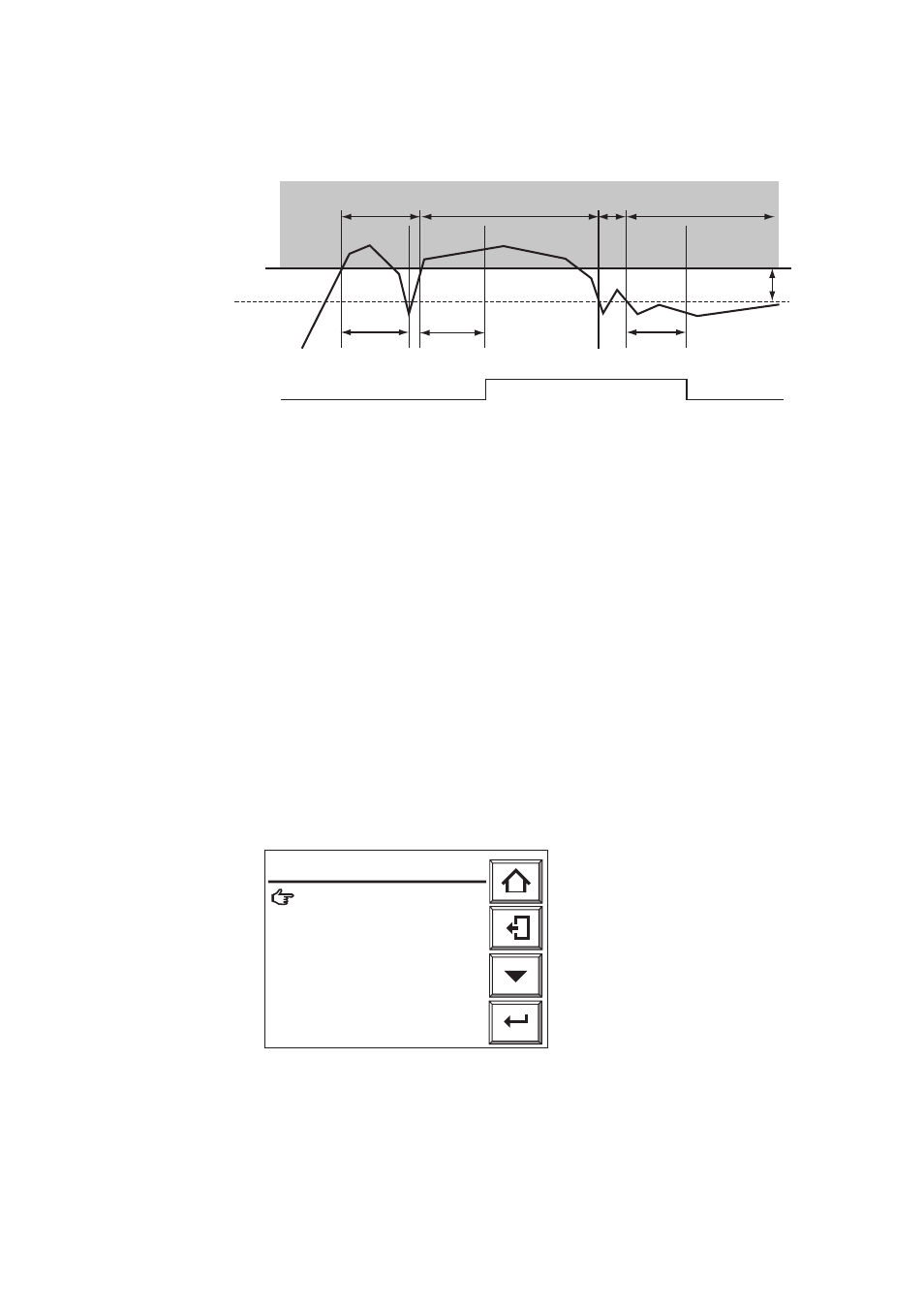
The action of delay and hysteresis are illustrated in Figure below. Alarm delay and
hysteresis settings apply to all alarm settings for all channels and all averaging groups.
Delay time:
5 seconds
7.5%
High-limit alarm setpoint
5.5%
Oxygen concentration
Alarm output ON
OFF
Hysteresis
2.0%
A
B
C
D
Alarm range
Delay time:
5 seconds
Delay time:
5 seconds
F8.4E.EPS
Fig.8.11 Alarm Output Action with Delay and Hysteresis
Fig.8.11 shows an example with high alarm setting of 7.5% O
2
, alarm delay of 5 sec.,
and hysteresis of 2% O
2
.
A . Although the measured value exceeds the high alarm setting, within the delay time
of 5 sec. it falls within (alarm setting
ᎏ hysteresis) so no alarm is output.
B. The measured value stays outside the alarm setting for longer than the delay time, so
an alarm is output, delayed by the delay time.
C . Although the measured value falls within (alarm setting
ᎏ hysteresis) it does not
stay there for the delay time, so the alarm is not released.
D. After the measured value falls within (alarm setting
ᎏ hysteresis) and stays there for
the delay time, the alarm is released.
appears.
2) Select [Commissioning] --> [Alarm setup] and the Alarm setup display (Fig.8.12)
appears.
Enter
F41E.EPS
Hysteresis: 0. 1 %O2
᭜
Contact delay: 3 s
᭜
Alarm set points
᭜
Except alarm ch.: Yes
Alarm setup
Fig. 8.12 Alarm setting